Connections, Figure 11, Hmt130 component board – Vaisala HMT130 User Manual
Page 25
Chapter 3 ________________________________________________________________ Installation
VAISALA ________________________________________________________________________ 23
Connections
1011-162
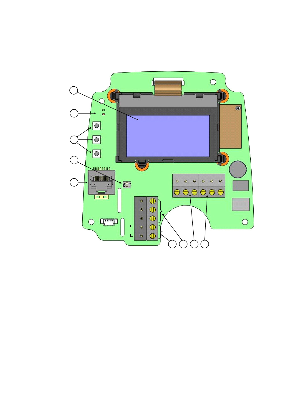
Figure 11
HMT130 Component Board
The following numbers refer to Figure 11 above:
1
= Optional LCD display
2
= Indicator LEDs
3
= Adjustment buttons
4
= RS-485 bus termination switch
5
= Service port
6
= Relay terminals
7
= RS-485 bus
8
= Analog outputs
9
= Power supply connectors
SERVICE PORT
ADJ
+
-
RH
T
485-
485+
GND
REL
C
A
L
SG
ND
CH
1
CH
2
S
H
IE
LD
V
IN
–
VI
N
+
485 TERM
SERVICE PORT
ADJ
+
-
RH
T
485-
485+
GND
REL
C
A
L
SG
ND
CH
1
CH
2
S
H
IE
LD
V
IN
–
VI
N
+
485 TERM
2
5
3
4
1
9
8
7
6
See also other documents in the category Vaisala Humidifiers:
- Calibration of Digital Transmitters with HMI41 (36 pages)
- Calibration of Series HMDW2030 and HMP130 Transmitter with HMI41 (14 pages)
- Calibration of Series HMDW6070 and HMP140 Transmitter with HMI41 (30 pages)
- HM34 (30 pages)
- HM40 (47 pages)
- HM44 (52 pages)
- HM70 (83 pages)
- HMD40 (1 page)
- HMD60 (4 pages)
- HMD70 (18 pages)
- HMDW110 (62 pages)
- HMDW80 (51 pages)
- HMI41 (74 pages)
- HMP41 (72 pages)
- HMK15 (39 pages)
- HMM100 (71 pages)
- HMM105 (23 pages)
- HMM211 (42 pages)
- HMM212 (36 pages)
- HMM213 (52 pages)
- HMP140 (28 pages)
- HMP155 (84 pages)
- HMP228 (115 pages)
- HMP230 (163 pages)
- HMP240 (130 pages)
- HMP260 (118 pages)
- HMP60 (71 pages)
- HMT100 (52 pages)
- HMT120 (87 pages)
- HMT140 (76 pages)
- HMT310 (88 pages)
- HMT310 (105 pages)
- HMT330 (209 pages)
- HMT360 (97 pages)
- HMT360 (63 pages)
- HMT360N (110 pages)
- HMW40 (1 page)
- HMW90 (110 pages)
- SHM40 (68 pages)
- RDP100 (14 pages)