Wiring, Wiring the ac bypass assembly – Outback Power Systems GS Load Center Installation Manual User Manual
Page 35
Wiring
900-0123-01-00 Rev B
33
Wiring the AC Bypass Assembly
The GSLC175-120/240, GSLC175-PV-120/240, GSLC175-230, and GSLC175-PV-230 each come
equipped with a maintenance bypass assembly. Alternately, they can be equipped with a bypass
assembly using the GS-IOB-120/240VAC or GS-IOB-230VAC accessory kit as appropriate. The accessory
kit should be installed according to its own instructions. Once installed, it can be wired by following
the steps shown in Figure 34 or Figure 35 .
The operation of the bypass assembly is discussed on page 34. A series of GSLC diagrams with the
bypass wiring (as well as the rest of both the AC and DC systems) are shown beginning on page 39.
These drawings show the utility grid circuit connected to the bypass assembly.
NOTE: Only one AC source may be bypassed with this assembly, even if two sources are present.
Bypassing multiple AC sources will usually connect the sources to each other.
WARNING: Shock Hazard or Equipment Damage
If multiple inverters are in use, see page 34 before attempting to install or use the
bypass assembly.
Bypassing multiple sources will usually connect the sources to each other, which may
damage one or both sources. It can otherwise result in power being routed to
inappropriate places.
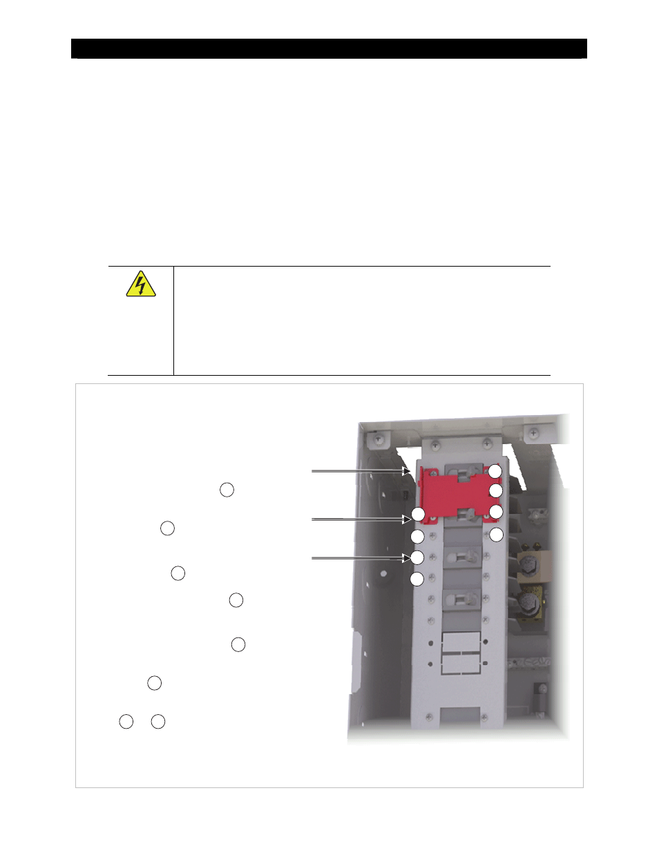
Figure 34
Maintenance Bypass Wiring (split-phase)
To wire the GS-IOB-120/240VAC
after installation:
1.
On the disconnect for the AC
source that will be used during
bypass, install a wire from the
upper pole as shown by
1
.
Connect it to the upper pole of
the inverter bypass switch as
shown by
2
.
2.
From the same disconnect,
install a wire on the lower pole
as shown by
3
. Connect it to
the lower pole of the inverter
bypass switch as shown by
4
.
3.
On the right side of the inverter
bypass switch, install a wire on
the lower pole as shown by
5
.
Connect it to the right side of
the lower pole on the output
switch
6
. Install a second
wire between the upper poles
of each switch as shown b y
7
and
8
.
Output
Inverter
Bypass
1
2
4
3
5
6
AC
Source
8
7