Installation, Bonding – Outback Power Systems GS Load Center Installation Manual User Manual
Page 26
Installation
24
900-0123-01-00 Rev B
Bonding
All GSLC models are equipped with a mechanical bond between AC neutral and ground. All models
that do not include the GFDI are also equipped with a mechanical bond between DC negative and
ground. These can be useful in stand-alone systems where no other bond is provided. If other bonds
are present, or if the GFDI is installed later, the GSLC bonds need to be removed.
WARNING: Shock Hazard
GSLC models purchased with the OutBack GFDI do not have a bond between negative
and ground. If the GFDI is manually installed (see page 18 and the GFDI manual), the bond
between must be removed. This must also be done if any other PV ground-fault device is
present that establishes its own negative-ground bond.
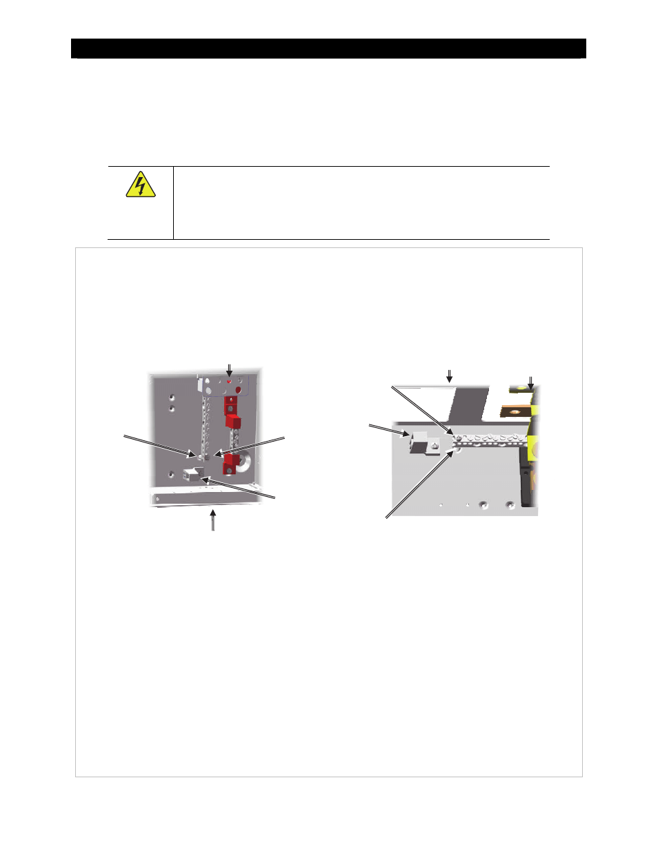
Figure
24
Removing Bonding Connections
Screw
TBB
Mount
DC Positive (+) Cable Plate
Neutral-Ground Bond
Negative-Ground Bond
Inverter
Negative (–)
Bus Bar
To remove either of the bond connections:
1.
Using a Phillips screwdriver, remove the screw
shown above. Remove the star washer with it.
2.
Remove the metal standoff beneath the bus bar.
The screw and bus bar provide the mechanical
bond to the chassis ground.
3.
Rotate the TBB mount. Insert the bus bar into the
open end of the TBB mount so that the TBB mount
supports the bus bar. It may be necessary to
loosen the TBB mount screw before rotating it.
4.
Retighten the screw and star washer to secure the
TBB mount.
Bottom of GSLC
Top of GSLC
The GSLC’s neutral bus bar is located
in the lower right portion of the GSLC.
The neutral-ground bond is
established at one end of the bar, near
the base of the GSLC.
TBB
Mount
Screw
NOTES:
If the TBB is connected directly to the
enclosure by a screw, then the bond is
connected.
If the TBB is held by the TBB mount and the
TBB mount is secured to the enclosure, the
bond is disconnected.
The installed Neutral TBB has white
insulators. A second Neutral TBB with blue
insulators is included in the kit for locations
where blue is standard.
The GSLC’s negative (–) bus bar is located
near the top of the GSLC. It is attached to
the inverter negative (–) bus and its shunt.
Standoff
Standoff