Dc wiring, Wiring, Inverter wiring – Outback Power Systems GS Load Center Installation Manual User Manual
Page 27: Battery wiring
Wiring
900-0123-01-00 Rev B
25
DC Wiring
WARNING: Shock Hazard
Ensure all circuit breakers or disconnect devices are turned off or disconnected
before connecting any wires.
Inverter Wiring
The DC disconnects are connected directly to the inverter using bus bars during the process of
mounting. See page 20 for more information.
Battery Wiring
The Radian inverter requires two positive (+) and two negative (–) cables for proper installation.
Consult the Radian Series Inverter/Charger Installation Manual for cable sizing and length
recommendations appropriate for the specific installation. (The GSLC bus connections may allow a
single larger conductor to be brought in from the battery, if sized correctly.)
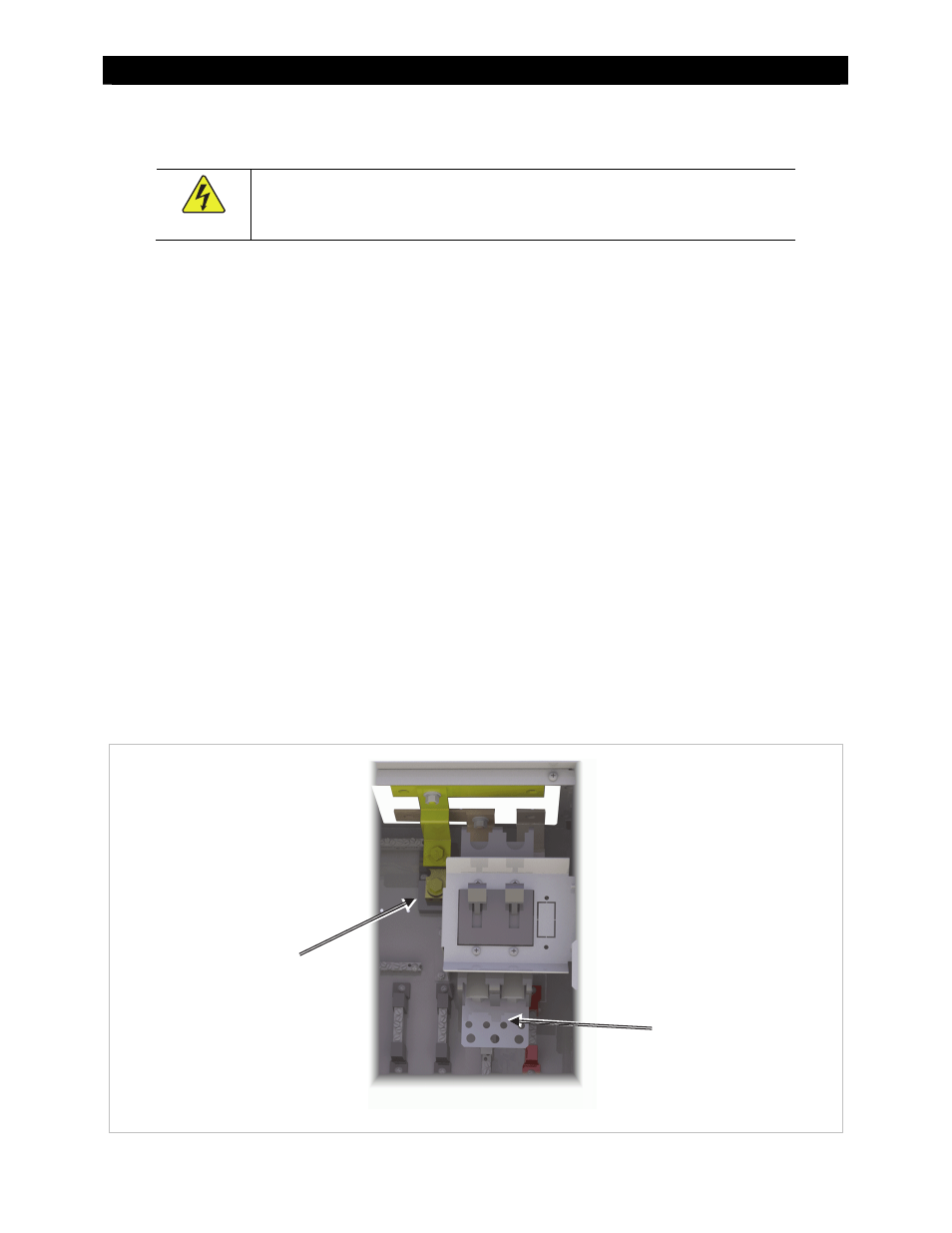
The battery positive (+) cables connect to the DC positive (+) wiring plate. This plate is located directly
beneath the main inverter disconnects. It is intended for several ring lugs to be bolted to it.
The smaller holes have a diameter of 0.31" (8 mm).
The larger have a diameter of 0.4" (10 mm).
The battery negative (–) cables connect to the pre-installed shunt. This shunt is located to the upper
left of the main inverter disconnect. It is designed for several ring lugs to be bolted to it, with
openings of 3/8" (10 mm) diameter.
See Table 1 on page 13 for required torque values.
Ensure DC disconnects are turned to the OFF position and all DC sources are disconnected (unbolt the
battery end of the wires) before proceeding.
See the inverter’s installation manual for additional information on battery wiring.
Figure
25
Battery
Connections
Shunt
DC positive (+) plate