Grounding, Wiring – Outback Power Systems GS Load Center Installation Manual User Manual
Page 25
Wiring
900-0123-01-00 Rev B
23
Wiring
Table 2
Terminal Bus Bar (TBB) Wire Size and Torque Requirements
Conductor Size
Torque Requirements
AWG mm2
In-lb Nm
#14 – #10
2.5 – 4
20
2.3
#8
6 – 10
25
2.8
#6 – #3
16 – 25
35
4.0
#2 35
40 4.5
#1 – 1/0
50
50
5.7
Grounding
WARNING: Shock Hazard
The unit must be connected to a grounded, permanent wiring system. If a bond is made
between neutral and ground, make sure only one bond is present in the AC system at any
time. The GSLC comes equipped with a neutral-ground bond. This bond may need to
be disconnected. Some codes require the bond to be made at the main panel only.
WARNING: Shock Hazard
For all installations, the negative (–) battery conductor should be bonded to the
grounding system at only one point. The GSLC comes equipped with a negative-
ground bond. This bond may need to be disconnected. If the OutBack GFDI is present, it
can provide the bond. See page 24.
IMPORTANT:
Most OutBack products are not designed for use in a positive-grounded system. If it is
necessary to build a positive-grounded system with OutBack products, contact OutBack
Technical Support at +1.360.618.4363 before proceeding. Additionally, consult the
online forum at www.outbackpower.com/forum/, where this subject has been
discussed extensively.
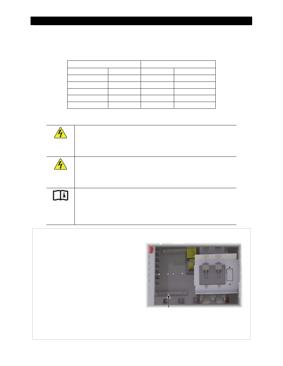
Figure 23
Grounding
The GSLC’s grounding TBB, which is bonded to
the GSLC chassis, is located to the lower left of
the main inverter disconnect. It accepts
conductor sizes from 1/0 to #14 AWG (50 mm
down to 2.5 mm).
This TBB accepts ground connections from the
Radian inverter, FLEXmax charge controllers, the
OutBack GFDI, the Grounding Electrode Conductor
(GEC) or external earth ground, and other
equipment.
See the Radian Series Inverter/Charger Installation
Manual for recommendations on ground
conductor sizing. Once the size is determined,
see Table
2 for required torque values.
Ground TBB