Installation, Installing the flexnet dc – Outback Power Systems GS Load Center Installation Manual User Manual
Page 28
Installation
26
900-0123-01-00 Rev B
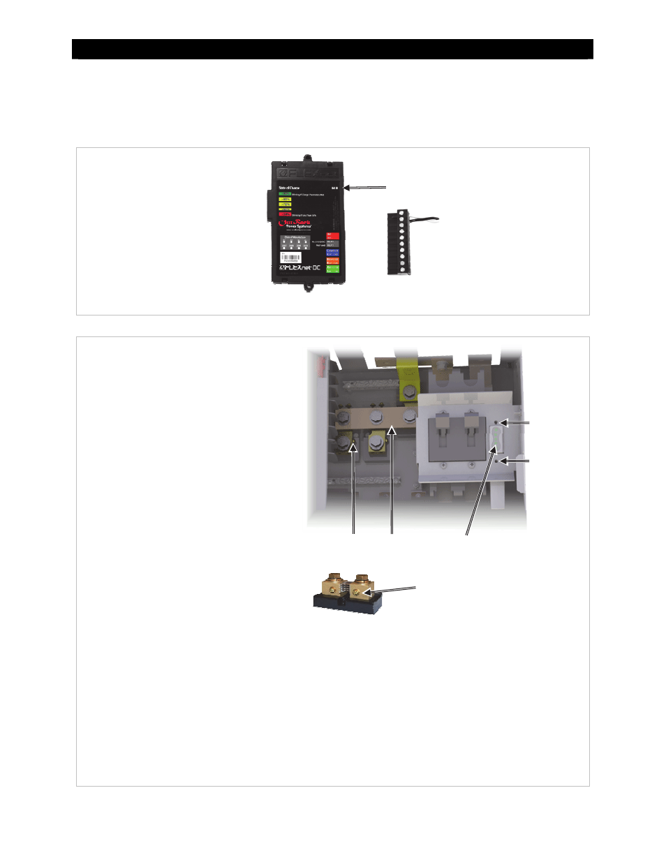
Installing the FLEXnet DC
The OutBack FLEXnet DC (FNDC), or a similar battery monitor, may be added to the GSLC for observing
DC current flow and providing battery state-of-charge information.
Figure
26
FNDC and Wiring Block
Figure 27
Installing the FNDC
HUB port
Wiring block
To install the FNDC :
1.
Assemble the FNDC wiring as shown in
the manual for the FNDC.
Attach sense wires to FNDC wiring
block and plug it into the FNDC.
Plug the CAT5 cable into the port
labeled HUB.
2.
Connect FNDC wiring to the GSLC.
The positive (+) and negative (-)
battery voltage sense conductors
should connect directly to the
battery bank.
The shunt sensing wires should
connect to the screws on each
shunt. It may be necessary to
remove the GS-SBUS to reach
the screws.
3.
Mount the FNDC by inserting it into
the opening to the right of the inverter
disconnects. It may be necessary to
hold it in place.
4.
Secure the FNDC with mounting
screws above and below. Tighten until
secure, but do not over-tighten.
Mounting
screws
FLEXnet DC
GS-SBUS
Mounting
screws
Shunt
screws
When connecting sensing wires: The end of the shunt
connected to the GS-SBUS is the negative (–) battery
connection and should be wired accordingly. The other end
of the shunt is the “device” or “load” end and should be
wired accordingly.
See the FLEXnet DC manual for more information on these
connections. See Figure 42 on page 40 for an example of
typical system wiring.
Shunt screws