Chassis airflow, Chassis airflow -17, Diagrams, refer to – Alcatel-Lucent OMNISWITCH 6800 User Manual
Page 43: Fer to
OmniSwitch 6800 Series Chassis and Hardware Components
Mounting the Switch
OmniSwitch 6800 Series Hardware Users Guide
June 2007
page 2-17
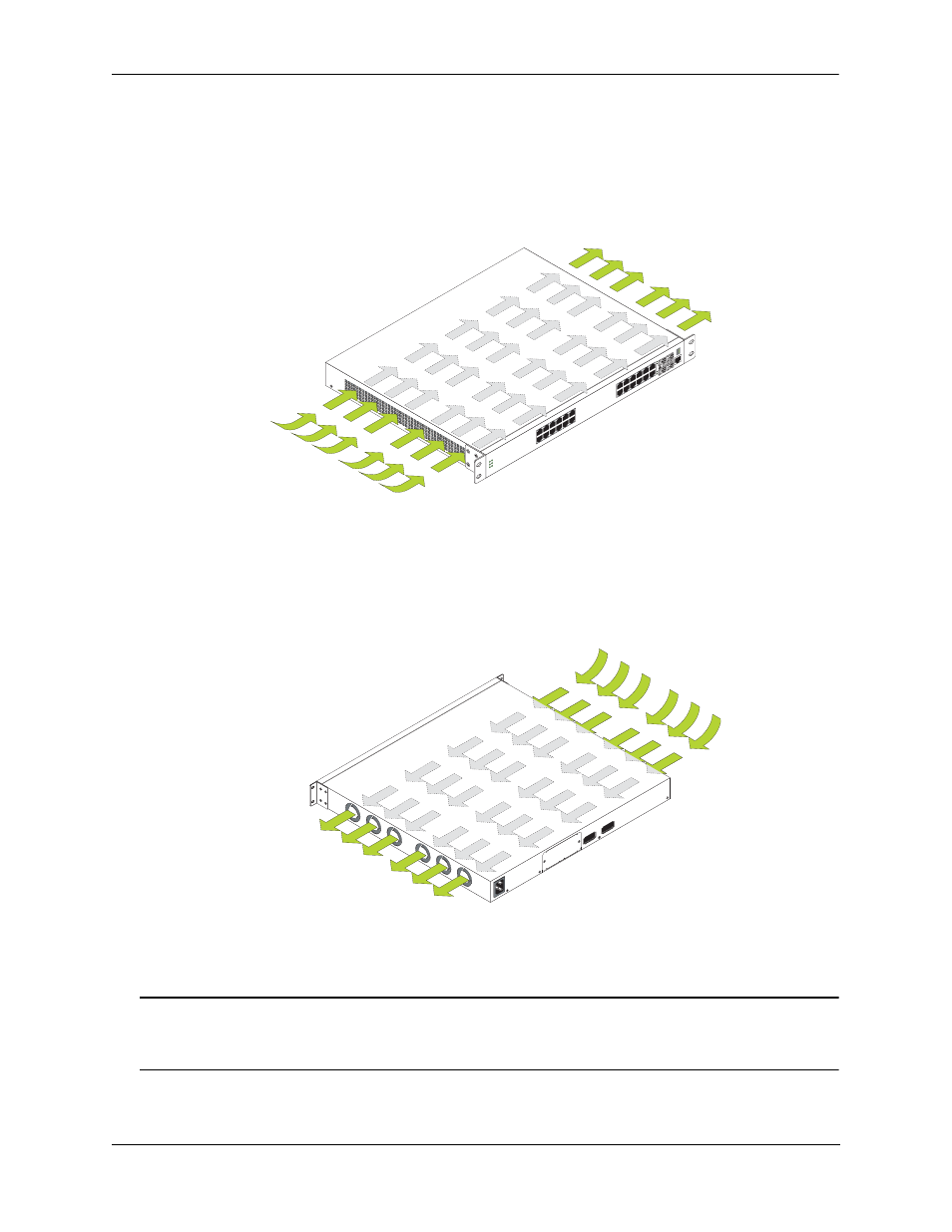
Chassis Airflow
The fans pull air from the air intake vent located at the left-hand side of the chassis. The air is directed
horizontally through the chassis and past the circuit board. Airflow is then exhausted through the fan vents
at the right-hand side of the chassis. Refer to the illustrations below for more information.
Important. Maintain a clearance of at least two inches at the left and right sides. Otherwise, airflow may
become restricted. Restricted airflow can cause your switch to overheat; overheating can lead to switch
failure. See
“Airflow Considerations” on page 2-16
for more information on chassis clearances.
OK
PW
R
FAN
TM
P
BPS
PRI
22
24
21
23
21
23
22
24
Con
sole
15
16
17
18
19
20
21
22
23
LIN
K/
AC
T
24
LIN
K/
AC
T
13
14
3
4
Sp
eed
2
5
6
7
8
9
10
11
12
Spe
ed
1
1. Air Intake. The six chassis
fans pull air from the main air
intake vent located at the left-
hand side of the chassis.
2. Airflow. The air from the
intake vent is directed
through the chassis past the
circuit board. This airflow
provides required cooling for
chassis components.
3. Air Exhaust. The airflow
is exhausted through the six
fan exhaust vents at the right-
hand side of the chassis.
Left Side Air Intake Vent
Right Side Fan Exhaust Vents
Air Intake Vent
Front of Chassis
Front of Chassis
Fan Exhaust Vents