Automatic supply dispenser analysis – Alliance Laundry Systems HX User Manual
Page 62
60
9001900
Section 3 Troubleshooting
© Copyright, Alliance Laundry Systems LLC – DO NOT COPY or TRANSMIT
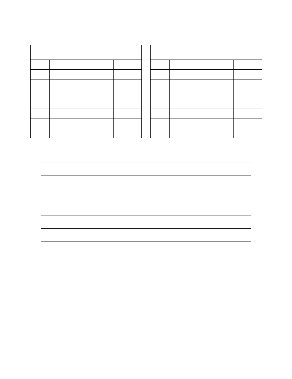
15. AUTOMATIC SUPPLY DISPENSER ANALYSIS
Run Program 38.
Run the cycle and, with the respective supply on the main display, refer to the following chart for the function
that should be occurring:
Cycle 38
Supply Setup
Cycle 38
Supply Setup
Step
Description
Min:sec
Step
Description
Min:sec
1
Warm Fill to Low Level
5:00
8
Warm Fill to Low Level
5:00
2
Supply 1
2:00
9
Supply 6
2:00
3
Supply 2
2:00
10
Supply 7
2:00
4
Supply 3
2:00
11
Supply 8
2:00
5
Supply 4
2:00
12
Supply 9
2:00
6
Supply 5
2:00
13
Wash 1 18/3 (80°F)
0:30
7
Drain 1
1:00
14
Drain 1
1:00
Supply
Function
Voltage
1
Turns on the water valve in compartment A of the
supply box.
N/A
2
Turns on the water valve in compartment B of the
supply box.
N/A
3
Turns on the water valve in compartment C of the
supply box.
N/A
4
Activates supply relay 1. Visibly inspect the relay to
see if it is closing and check for voltage.
220 Volts between terminals 1 and14
5
Activates supply relay 2. Visibly inspect the relay to
see if it is closing and check for voltage.
220 Volts between terminals 3 and14
6
Activates supply relay 3. Visibly inspect the relay to
see if it is closing and check for voltage.
220 Volts between terminals 5 and14
7
Activates supply relay 4. Visibly inspect the relay to
see if it is closing and check for voltage.
220 Volts between terminals 7 and14
8
Activates supply relay 5. Visibly inspect the relay to
see if it is closing and check for voltage.
220 Volts between terminals 9 and14
9
Activates supply relay 6. Visibly inspect the relay to
see if it is closing and check for voltage.
220 Volts between terminals 11 and14