Lokar Column Shift Linkage For Ford AOD, 4R70W, and AODE User Manual
Page 3
Page 3
Step 13: AODE and 4R70W Only: Install the new Lokar flange onto the
selector shaft. If using the original selector shaft, use the origi-
nal nut or bolt to retain the flange. If using the Lokar selector
shaft, install the supplied 3/8"-16 x 3/4" lock bolt into the
selector shaft to retain the flange
All: Install the trans arm onto the new selector shaft or flange
using the three #8-32 x 3/8" button head bolts and lock
washers. The trans arm should be installed at approximately
the 7:30 position as a starting point with the transmission in
"PARK". Fig. 13 The trans arm may need to be repositioned
depending on your particular steering column. The 3/16" diam-
eter hole that is part way up the arm next to the slot should be
towards the back of the transmission. This hole is used with a
Lokar Shift Indicator Kit.
Step 14: AOD Only: Verify that the internal T.V. lever is still aligned with
the T.V. piston. Install the external T.V. lever, following the
instructions that are provided in that kit. This will prevent the
internal T.V. lever from becoming misaligned.
All: (Disregard this step if you did not have to remove the pan.)
Reinstall the filter and the transmission pan. Fill with the
appropriate amount of transmission fluid.
Step 15: The column shift arm could be one of several different designs,
and the type of column shift arm you have will determine how
the Delrin® bushings will be positioned. If the raised shoulder
in the center of the provided Delrin® bushings will fit inside
the hole in the column shift arm, then the Delrin® bushings
will be installed with the raised shoulders facing each other
inside the column shift arm. If the raised shoulder in the cen-
ter of the provided Delrin® bushings will
NOT fit inside the hole
in the column shift arm, then the Delrin® bushings will be
installed with the raised center shoulders facing outwards.
NOTE: Some aftermarket steering columns may require that
you drill out the shift linkage lever to fit the bushings. The new
hole diameter should be 0.625" (5/8").
Attach the 5/16"-24 female rod end to the steering column
arm with the 5/16"-24 X 1-1/2" hex head bolt. Install a small
flat washer onto the bolt first, and then slide on the female
rod end. Next install the large diameter flat washer, and one
Delrin® bushing facing the proper direction. Insert the bolt
through the steering column arm, and then install the other
Delrin® bushing and small flat washer. Secure it all using the
5/16"-24 nylock nut as shown in
Fig. 14.
NOTE: These items can be installed in the reverse order if nec-
essary for clearance or proper alignment.
Step 16: Thread the stainless steel rod into the rod end on the steer-
ing column arm and up to the jam nut, leaving about 1/4" of
threads exposed beyond the jam nut.
Step 17: Check to make sure that nothing will interfere with connecting
the stainless steel rod to the adjustable trans arm. If required,
the stainless steel rod can be bent to clear other components,
starting at the steering column end.
Step 18: Make sure both the shifter lever on the column and the trans-
mission are in Park. Line up the transmission end of the stain-
less steel rod with the center of the slot in the trans arm, and
mark the stainless steel rod at the center of the trans arm slot.
Cut the stainless steel rod 1-3/4" back towards the column end
from your mark, using a metal cutting saw or cutoff wheel.
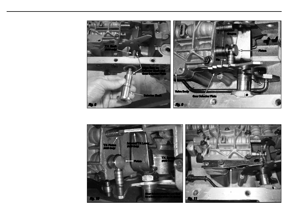
T.V. Shaft
(AOD only)
Selector Shaft
T.V. Piston
(AOD Only)
T.V. Spring
(AOD Only)
Internal T.V. Lever
(AOD Only)
Gear Selector Plate
Valve Body
Pin
Groove
Piston
Piston
(Gear Selector placed in Low Gear
for a better view of the T.V. Spring)
Align flats on
Selector Shaft and
Gear Selector Plate
Fig. 8
Fig. 9
Fig. 10
Fig. 11
Roller Spring
Column Shift Linkage Installation Instructions for Ford AOD, 4R70W, and AODE