Lokar Automatic Trans Mount Shifter 700-R4 , 4L60, and 4L60E User Manual
Page 2
Page 2
© 2013 Lokar, Inc.
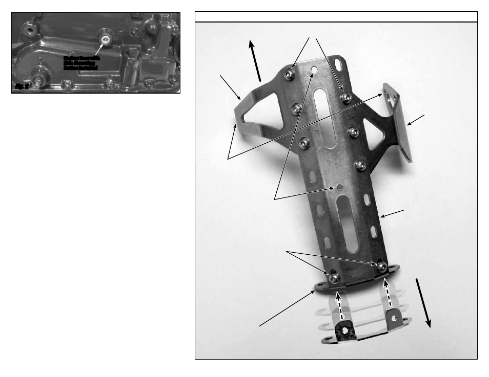
Fig. 3
The shifter is designed to lock in Park and in Neutral. You must depress the release button in
the top of the shifter knob in order to shift out of Park or Neutral. The release button will only
be flush with the top of the shift knob when the shifter is in Park or Neutral.
To shift from Park directly to Overdrive, depress the release button and then hold it down while
moving the shifter lever, and the shifter will automatically stop in the Overdrive position. Once
you release the button, then the shifter will allow you to move the lever into 3rd gear. You must
depress the button again to shift down into 2nd gear or 1st gear.
These instructions assume that you have full access to the transmission when the shifter instal-
lation is begun, with the transmission removed from the vehicle, or the vehicle body removed
from the chassis.
Step 1: If your vehicle already has a shifter of any type installed, disconnect all shifter linkage
and remove the shifter and its related hardware (neutral safety switch, back-up light
switch, etc.).
Step 2: In the Lokar shifter kit you are supplied with two aluminum side mounting buttons that
are approximately 5/8" in diameter. Your transmission has two round, hollow bosses cast
into the case, one on the driver’s side and one on the passenger’s side. Clean any paint
or debris out of these bosses, and install the side mounting buttons into the bosses with
the flat side in toward the transmission case.
Fig. 2
Step 3: The main plate has two 5/16"-24 tension set screw holes. One set screw hole is in the
center of the main plate, and the other set screw hole is at one end of the main plate.
The main plate will be installed so that the end of the main plate that has a set screw
hole will go to the front (towards the engine), and the end that does not have a set screw
hole will go to the rear.
The left side bracket and right side bracket bolt directly to the main plate.
NOTE: The
right side bracket will be offset rearward on the main plate by one slot, compared to the left
side bracket. Attach the side brackets to the underside of the main plate as shown in
Fig. 3, using three 5/16"-24 x 1/2" button head bolts and lock washers on each side.
DO NOT TIGHTEN AT THIS TIME.
Step 4: (2 Wheel Drive transmissions) Attach the rear mounting bracket to the underside of
the main plate with the bracket ears pointing to the front of the transmission (toward
the engine) as shown in
Fig. 3, using two 5/16"-24 x 1/2" button head bolts and lock
washers.
DO NOT TIGHTEN AT THIS TIME.
Note: The 4L60E kit comes with two rear mounting brackets. Use part # 6852 if your tail-
housing is attached to the transmission with 4 bolts. Use part # 6952 if your tailhousing
uses 6 bolts. The part number is stamped into each bracket.
(4 Wheel Drive Transmissions) You will not be using the rear mounting bracket.
Step 5: (2 Wheel Drive transmissions) Remove the top two tail housing bolts from the transmis-
sion. Install the mounting bracket assembly onto the transmission by first installing two
M10 x 35mm button head bolts with lock washers through the rear mounting bracket
and into the transmission at the tail housing.
(4 Wheel Drive Transmissions) Install the 5/16"-24 x 5/8" tension set screws with jam
nuts into the tension set screw holes at the front and in the center of the shifter main
plate. Set the mounting bracket assembly into place on top of the transmission.
Fig. 4
Step 6: Install the 3/8"-24 x 1" tension set screws through the side brackets into each side
mounting button, but do not tighten.
Fig. 2
Left Side
Bracket
Hollow Boss with
Side Mounting
Button Installed
Right Side
Bracket
Main
Plate
Rear
Mounting
Bracket
(2 Wheel Drive Only)
5/16"-24
Tension Set
Screw Holes
3/8"-24
Tension Set
Screw Holes
5/16"-24 x 1/2" Button Head Bolts
and Lock Washers
(Three Each Side)
5/16"-24 x 1/2"
Button Head Bolts
and Lock Washers
(2 Wheel Drive Only)
Mounting Bracket Assembly
Front of
Vehicle
Rear of
Vehicle