Lokar Automatic Trans Mount Shifter Ford AOD, 4R70W, and AODE User Manual
Page 5
INS0087 Rev. 06/03/14
Page 5
© 2005 Lokar, Inc.
Step 13: The threaded rod will connect the quad lever to the trans arm. Check to make sure that nothing will interfere with
the travel of the threaded rod. If there is any interference, the threaded rod can be bent slightly as needed. On a
4R70W or AODE it may be necessary to adjust the threaded rod to clear the MLPS (manual lever position switch
or neutral safety switch).
Verify that both the shifter and the transmission are in the Park position. Measure center-to-center between the
1/4" holes in the trans arm on the transmission and the quad lever on the shifter. Subtract 1-3/4".
Fig. 8 This is
the length you will cut the threaded rod to. Use a hacksaw or other metal-cutting saw to shorten the threaded rod.
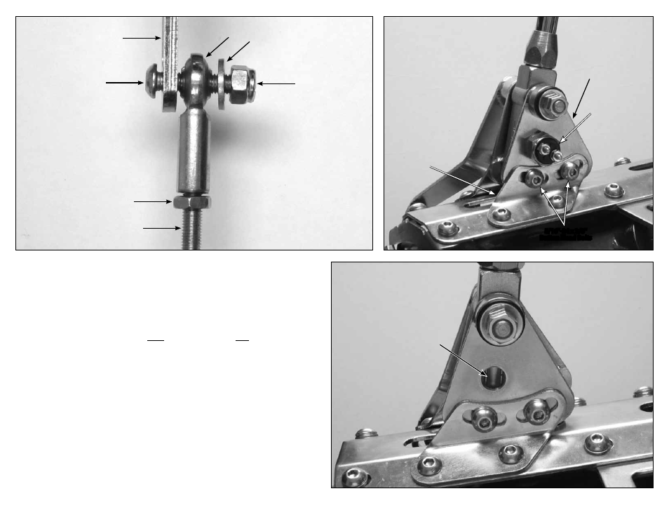
Step 14: Verify that both 1/4"-28 jam nuts are on the threaded rod, and install a rod end onto each end of the threaded
rod. Attach the threaded rod assembly to the
outside of the quad lever and to the inside of the trans arm using
the 1/4"-28 x 1" button head bolts, flat washers, and nylock nuts as shown in
Fig. 9 and Fig. 10. The button head
bolts can be installed from either direction, but make sure the rod end is sandwiched between the flat washer and
the quad lever or trans arm.
Step 15: Check the adjustment of the shifter by placing the shifter all the way forward into the Park position. Make sure
that the release button still moves up and down freely. The release button should be flush with the knob in Park
and Neutral. In the Reverse position, you cannot pull the lever back into Neutral without depressing the release
button.
While the shifter is in the Park position, make sure the transmission is firmly in the "Park" detent, with no
tension on the threaded rod. You can verify this by removing the 1/4"-28 x 1" button head bolt with nylock nut
that attaches the rod end to the quad lever or trans arm at either end of the threaded rod. Make sure the hole in
the rod end exactly aligns with the hole in the quad lever or trans arm. The bolt should pass freely through both
holes at the same time without binding. Do not force the holes to line up.
If the holes are not aligned, screw the rod end in or out just enough to be able to slide the bolt in and out without
putting tension on the threaded rod. Make sure that the quad lever and trans arm do not move during the
adjustment procedure. Use this adjustment routine until the bolt will pass freely in and out of both the rod end
and the quad lever or trans arm. Reinstall the 1/4"-28 nylock nut and the flat washer in its proper position onto
the bolt, and tighten.
Once you have the shifter adjusted correctly, tighten the jam nuts on the threaded rod.
Fig. 10
Fig. 11
Fig. 12
1/4"-28 x 1"
Button Head Bolt
Switch Plate
Neutral Safety
Switch and
Washer
Center Groove
in Shifter Body
Rod End
NOTE: Bolt can be installed from
either side. Make sure the Rod
End is sandwiched between the
Flat Washer and Trans Arm.
Threaded Rod
1/4"-28 Jam Nut
Trans Arm
1/4"-28
Nylock Nut
Flat Washer
Right Side
Banana
Bracket
5/16"-24 x 3/8"
Button Head Bolts