Lokar Automatic Trans Mount Shifter Ford AOD, 4R70W, and AODE User Manual
Page 4
INS0087 Rev. 06/03/14
Page 4
Step 10: Make sure the two 5/16"-24 x 3/8" button head bolts that attach the left side banana
bracket to the shifter assembly (in the curved, slotted holes) are tight. Before tightening the
shifter assembly down to the main plate, move the shifter through all the gear positions.
Make sure that the shifter lever and knob will not come in contact with the dash or the seat.
The shifter assembly can be tilted forward or backward if needed by loosening the 5/16"-24 x 3/8"
button head bolts in the curved, slotted holes in the left side banana bracket.
Fig. 6
If you ever disassemble the shifter assembly, be sure that the 5/16"-24 x 3/8” button head
bolts and lock washers are put back into the curved, slotted holes in the banana brackets.
Installing longer bolts will prevent the shifter from operating.
NOTE: If you find after installation that the shape or length of the shifter lever is not suitable
for your application, Lokar has a number of different styles and lengths of shifter lever
replacement kits available for purchase separately through our dealer network.
Step 11: Put the shifter into the Park position and check the position of the quad lever. It will need
to be pointing to approximately the 4:30 - 5:00 position. If it is not, loosen the set screw in
the top of the quad lever with a 1/8" Allen wrench and slide the quad lever off of the shaft.
Reposition it on the shaft at approximately the 4:30 - 5:00 position, and retighten the set
screw.
Fig. 6
NOTE: If your shifter is placed near the front of the bracket assembly, you may need to
position the quad lever slightly higher, such as at the 4:00 position instead. This will help
prevent over-centering the trans arm.
Step 12: If the provided Lokar Selector Shaft and Trans Arm were not installed before beginning the
shifter installation, install them now, following the instructions that came with that kit.
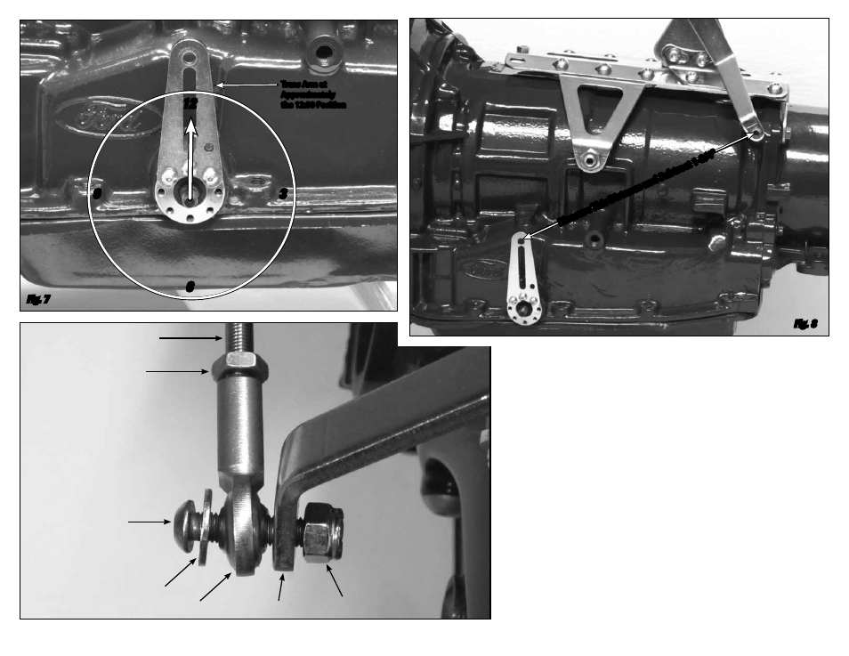
Place the trans arm in the Park position with the top of the lever pointing up, at
approximately the 12:00 position.
Fig. 7
Fig. 7
Fig. 9
Trans Arm at
Approximately
the 12:00 Position
Threaded Rod
NOTE: Bolt can be installed from
either side. Make sure Rod End
is sandwiched between the Flat
Washer and Trans Gear Lever.
1/4"-28 Jam Nut
1/4"-28 x 1"
Button Head Bolt
Flat
Washer
Rod End
Quad Lever
1/4"-28
Nylock Nut
Measur
e This Distanc
e and Subtr
act 1-3/4"
Fig. 8
6
12
3
9