Chapter five - scsi bridge electronics, 9 setup display format, 10 setup overview – HP NonStop G-Series User Manual
Page 23
Chapter Five - SCSI Bridge Electronics
When the desired tape density appears, push the mode switch to select it. The selected setting is used until
the unit is power cycled or reset. These choices are offered:
C0
= Compressed format
40
= Uncompressed format
FF
= Density controlled by the host software
Note: The setting from the last change of tape density is used as the default start-up value. The density
can be changed on a tape-by-tape basis any time the tape is at BOT during normal Performance
display operation.
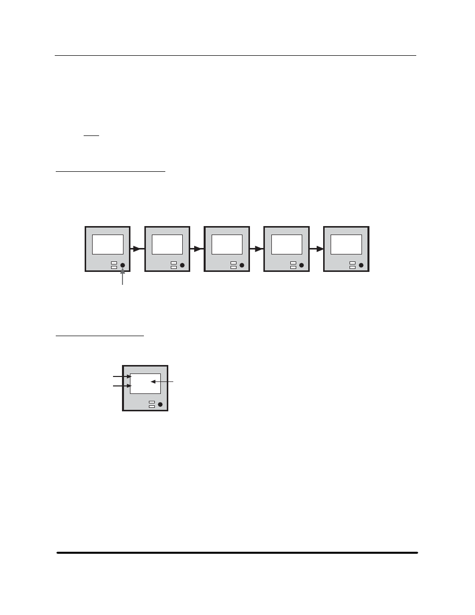
5.9
Setup Display Format
Configuration of the electronics is accomplished by using the mode switch. All values are retained in
nonvolatile memory. There are three setup menus: Setup 1 and Setup 2 contain configuration items and
Setup 3 contains diagnostic and special utilities. Enter the setup menus by holding in the mode switch while
powering up the unit. The menu display system consists of the following hierarchy:
Mode
Switch
*Set-Up*
Release
Button
to Start
Enter
Set-Up 1
PRESS to
Select
Enter
Set-Up 2
PRESS to
Select
Enter
Set-Up 3
PRESS to
Select
Exit
Set-Up
PRESS to
Select
Figure 24
LCD setup menus
5.10 Setup
Overview
Within each menu, the individual items generally take this format on the four-line LCD:
LCD Setup Format
SCSI ID:
[00]
PRESS to
Alter
Parameter
Setting
Instruction
Figure 25
LCD setup format
•PARAMETER
denotes the configuration being reviewed or edited.
•SETTING
(in
SETUP 1
and
SETUP 2
) is the value that you can change.
•INSTRUCTION
describes what action should be taken if the mode switch is pressed. If the mode switch
is inactive for four seconds, the display changes. In general, the menu system is designed to display the
current setting continuously. The instruction
PRESS to Alter
allows the operator to alter the value.
HP StorageWorks DAT 72 (Model 5242-2SE) User's Guide
19
HP Part Number 528297-003 July 2005