Chapter five - scsi bridge electronics – HP NonStop G-Series User Manual
Page 19
Chapter Five - SCSI Bridge Electronics
5.4
Display Unit LEDs
The display unit has two LEDs, one green and one amber. The green LED indicates that data compression
is active. The amber LED is a user-programmable, error-alert indicator that lights when the error-rate
percentage reaches a predetermined value. This value can be set or altered using the mode switch in
conjunction with the setup menus.
5.5
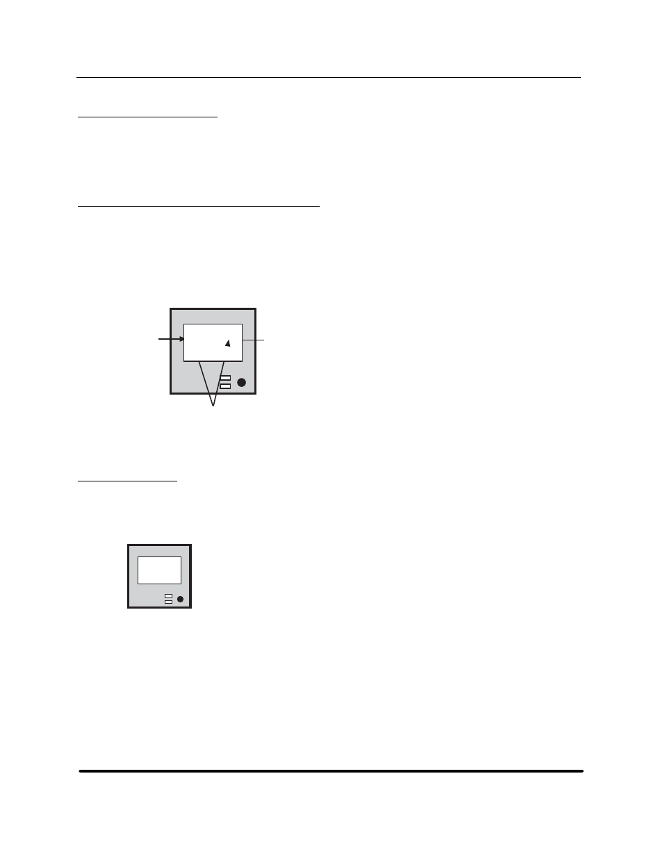
Understanding the Capacity Bar Graph
The capacity bar graph dynamically tracks remaining and consumed capacities. It updates dynamically
during read and write operations. Beginning with the native capacity of the cartridge, as reported by
the tape drive after a cartridge is loaded, Infourmm applies the average compression ratio (if any),
computes the then current maximum capacity, and displays the bar graph by incrementing the
appropriate number of vertical bars between the empty icon and the full icon. There are thirty vertical
bars, each equating to approximately 3.33% percent of total capacity.
Capacity
Indicators
Read
E F
ECC Rate
0.0%
Full Icon
Empty Icon
Figure 13
Understanding the capacity bar graph
5.6 Initial
LCD
After applying power to the unit, Infourmm attempts to find the drive at the tape ID. Typically,
tape drives require a few seconds to perform self-test before responding. The unit is not selectable
to the host during this period.
InFourmm
========
Power-on
SelfTest
Initial Power-Up Screen
Figure 14
LCD at startup
When the drive is found, the LCD presents the tape-drive ID and firmware level on the top two lines and
the product name, firmware level, and SCSI ID on the bottom two lines. The unit is now selectable to the
host as a device occupying the displayed SCSI ID.
HP StorageWorks DAT 72 (Model 5242-2SE) User's Guide
15
HP Part Number 528297-003 July 2005