Control box assembly – ADC Phase 5 Microprocessor AD-170 User Manual
Page 7
450126 - 8
www.amdry.com
7
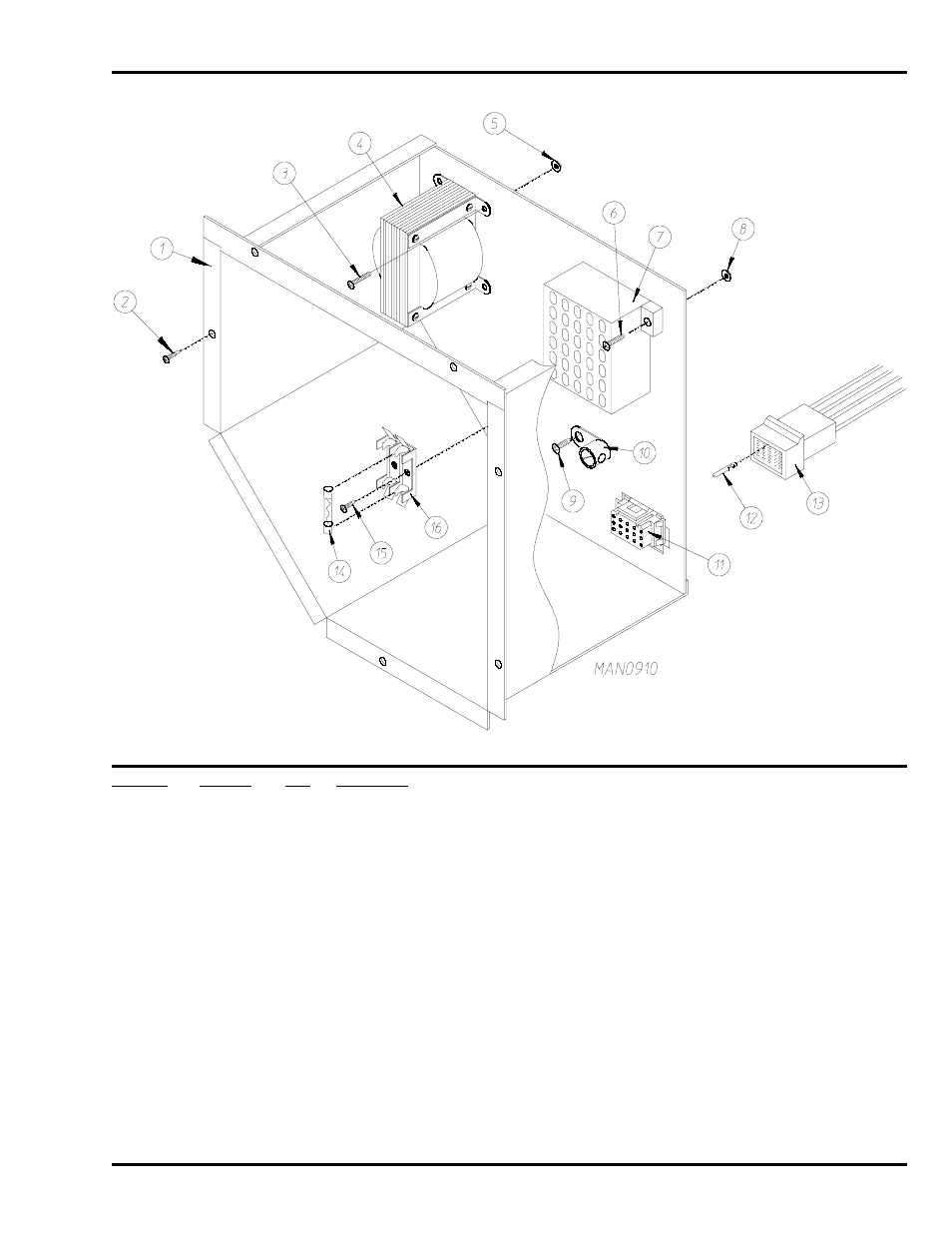
Control Box Assembly
Illus. No.
Part No.
Qty.
Description
1
820940
1
Control Box Assembly Complete
(includes illus. nos. 1, 2, 6 through 10, 14, 15, and 16)
2
150301
6
#8-32 x 7/16” Phillips Round Head TEK Screw
3
150100
2
#8-32 x 1/2” Round Head Machine Screw
4
141403
1
24 VAC Transformer
5
151001
2
#8-32 Pal Nut
6
150002
2
#6-32 x 1” Round Head Machine Screw
7
120715
1
30-Position Terminal Block
8
151000
2
#6-32 Pal Nut
9
150415
1
#10-16 x 1/2” Phillips Round Head Crimptite Screw
10
121010
1
L-70 Ground Lug
11
122626
1
15-Pin Socket Connector
12
122704
14
Pin Terminal
13
122625
1
15-Pin Connector
14
136057
2
1/2-Amp (Slo-Blo) Fuse
15
150301
1
#8-32 x 7/16” Phillips Round Head TEK Screw
16
136008
2
Fuse Block / Strip
—
122800
1
Microprocessor (female) Pin Extraction Tool
—
122801
1
Pin / Socket Extraction Tool