ROTRONIC HF65 User Manual
Page 19
E-M-HF63_65-V1_11
Rotronic AG
Bassersdorf, Switzerland
Document code
Unit
Instruction Manual
Document Type
HygroFlex HF63/HF65 Humidity Temperature
Transmitters: User Guide
Document title
Page 19 of 34
© 2008; Rotronic AG E-M-HF63_65-V1_11
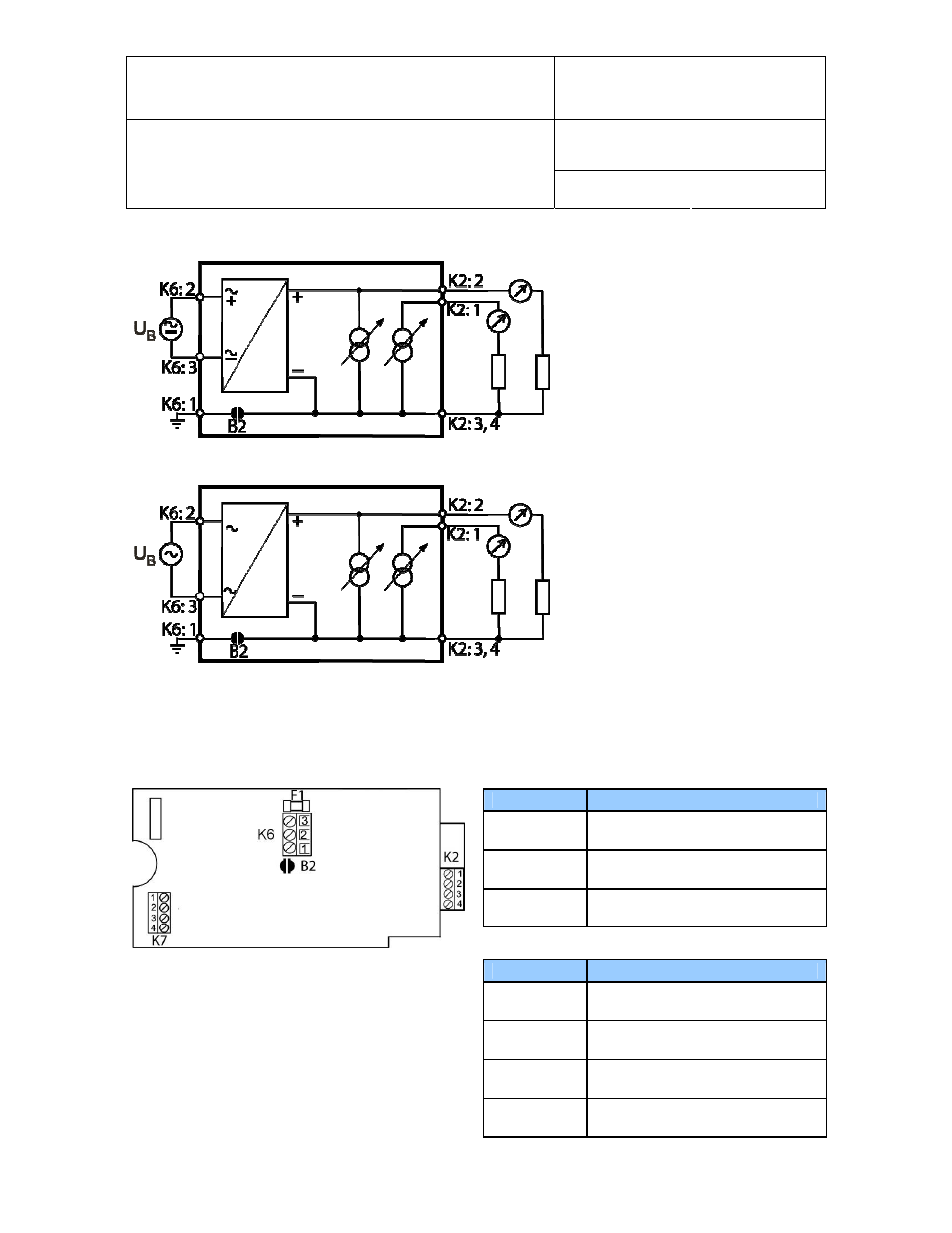
Electrical diagram 15 to 40 VDC or 12 to 28 VAC power supply with current outputs
Electrical diagram 85 to 265 VAC power supply with current outputs
The maximum permissible cable length, connecting the unit to other devices, is determined by the total
resistance resulting from the addition of the cable resistance and that of the devices connected in series with
the unit. This resistance should not exceed 500 ohms.
Terminal block diagram
Terminals
Description
K6-1: -►
General ground (see note below)
K6-2: +
Power supply: 15…40 VDC (+)
or VAC - Phase
K6-3: -
Power supply (-) or VAC - neutral
Terminals
Description
K2-1: OUT 1
Relative humidity or dew point (+)
K2-2: OUT 2
Temperature output (+)
K2-3: GND
Ground (tied with other GND)
K2-4: GND
Ground (tied with other GND)