Mechanical installation, General guidelines, 5mechanical installation – ROTRONIC HF65 User Manual
Page 14: 1 general guidelines
E-M-HF63_65-V1_11
Rotronic AG
Bassersdorf, Switzerland
Document code
Unit
Instruction Manual
Document Type
HygroFlex HF63/HF65 Humidity Temperature
Transmitters: User Guide
Document title
Page 14 of 34
© 2008; Rotronic AG E-M-HF63_65-V1_11
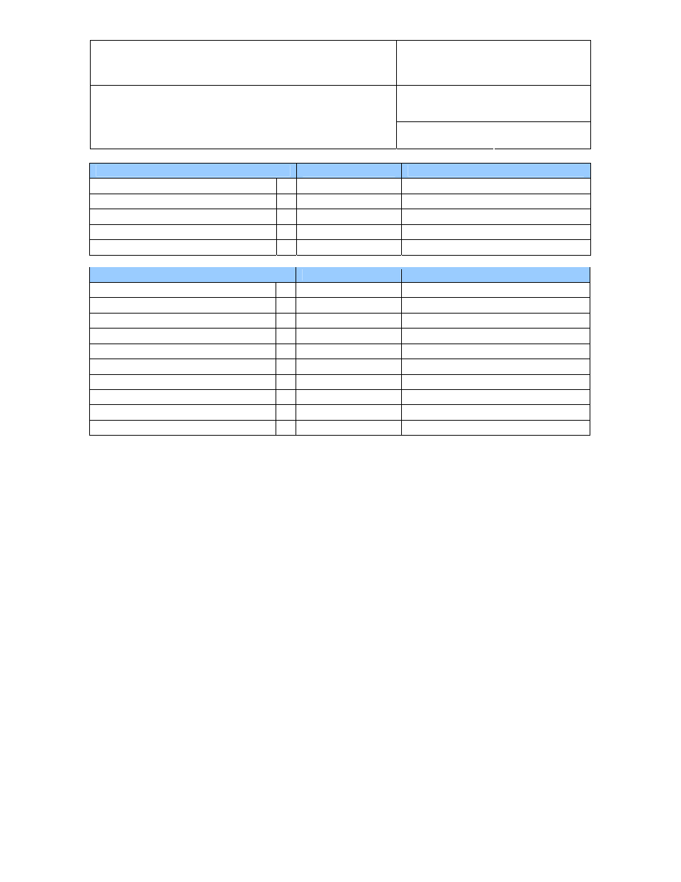
Configurable Settings
Applicability
Factory default
Trend indicator (display)
HF63, HF65
Enabled
Communication protocol
HF65
RO-ASCII
RS-485 address
HF65
0
TCP/IP settings
HF65
See document E-M-TCPIP-Conf
Device name
HF63, HF65
Instrument model
Functions
Applicability
Factory default
Humidity / temperature adjustment
K HF63, HF65
Device write protection
HF63, HF65
Disabled
Menu access from keypad
HF63, HF65
Enabled
Limit humidity output to 100 %RH
HF63, HF65
Enabled
Out-of-limit value digital / display alarm
HF63, HF65
Disabled
Data recording
K HF63, HF65
Enabled (loop mode – 10 min. interval)
Automatic humidity sensor test
HF63, HF65
Disabled
Humidity sensor drift compensation
HF63, HF65
Disabled
Fail safe mode
HF63, HF65
Disabled
Simulator mode
HF63, HF65
Disabled
o
For a detailed description of all AirChip 3000 / HF6 main functions see document E-T-AC3000-DF-V1
o
Instructions regarding the configuration of the HF6 and access to its functions are provided in the
following manuals:
E-M-HW4v2-F2-008
E-M-HW4v2-Main (§ 6.5)
E-M-HW4v2-DR-001
E-M-HW4v2-A2-001
E-M-AC3000-CP
.
o
Instructions for configuring the TCP/IP settings of the HF65, are provided in document
E-M-TCPIP-Conf
o
The factory default setting for dew / frost point calculation is frost point below freezing
5
Mechanical installation
5.1 General guidelines
Relative humidity is extremely dependent on temperature. Proper measurement of relative humidity requires
that the probe and its sensors be at exactly the temperature of the environment to be measured. Because of
this, the location where you choose to install the probe can have a significant effect on the performance of the
instrument. The following guidelines should guarantee good instrument performance:
a) Select a representative location: install the probe where humidity, temperature and pressure
conditions are representative of the environment to be measured.
b) Provide good air movement at the probe: air velocity of at least 200 ft/ minute (1 meter/second)
facilitates adaptation of the probe to changing temperature.