Hf6 enclosure, Installation of the enclosure and probe, 2 hf6 enclosure – ROTRONIC HF65 User Manual
Page 15: 3 installation of the enclosure and probe
E-M-HF63_65-V1_11
Rotronic AG
Bassersdorf, Switzerland
Document code
Unit
Instruction Manual
Document Type
HygroFlex HF63/HF65 Humidity Temperature
Transmitters: User Guide
Document title
Page 15 of 34
© 2008; Rotronic AG E-M-HF63_65-V1_11
c) Avoid the following: (1) Close proximity of the probe to a heating element, a cooling coil, a cold or
hot wall, direct exposure to sun rays, etc. (2) Close proximity of the probe to a steam injector,
humidifier, direct exposure to precipitation, etc. (3) Unstable pressure conditions resulting from
excessive air turbulence.
d) Immerse as much of the probe as possible in the environment to be measured.
e) Prevent the accumulation of condensation water at the level of the sensor leads. Install the
probe so that the probe tip is looking downward. If this is not possible, install the probe horizontally.
5.2 HF6 enclosure
The HF6 enclosure consists of a base and a cover held together with 4 screws. To open the enclosure, use a
metric 3 mm hex key. Prior to re-assembling the enclosure, verify that the red seal is sitting properly in its
groove on the base.
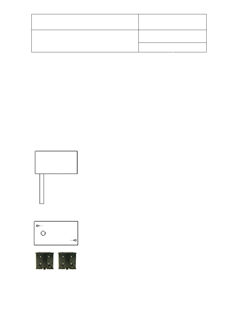
5.3 Installation of the enclosure and probe
Mounting position of the enclosure
The enclosure of the HF6 is designed to be mounted in a horizontal position as
illustrated here for the HF6 type W
Mounting hardware for the enclosure (HF6 type W and HF6 with cable probe)
Method 1: The HF6 is supplied with 2 screws, 2 drywall anchors and two
rubber washers. The base of the enclosure has 2 screw-wells (see drawing)
that are normally closed at the bottom. Use the template provided with the HF6
to drill mounting holes in the wall and insert the drywall anchors. Place a rubber
washer on each screw. Insert a screw in each well and push to open the
bottom of the well.
Method 2: When a DIN-rail (35 mm / 1 3/8”) is available use part AC5002 (not
included). This is a DIN-rail mounting kit consisting of 2 clamps that attach to
the back of the enclosure with the screws provided.