Wiring, Hf631 to hf63a: 3-wire analog transmitter – ROTRONIC HF65 User Manual
Page 18
E-M-HF63_65-V1_11
Rotronic AG
Bassersdorf, Switzerland
Document code
Unit
Instruction Manual
Document Type
HygroFlex HF63/HF65 Humidity Temperature
Transmitters: User Guide
Document title
Page 18 of 34
© 2008; Rotronic AG E-M-HF63_65-V1_11
6.4 Wiring
6.4.1
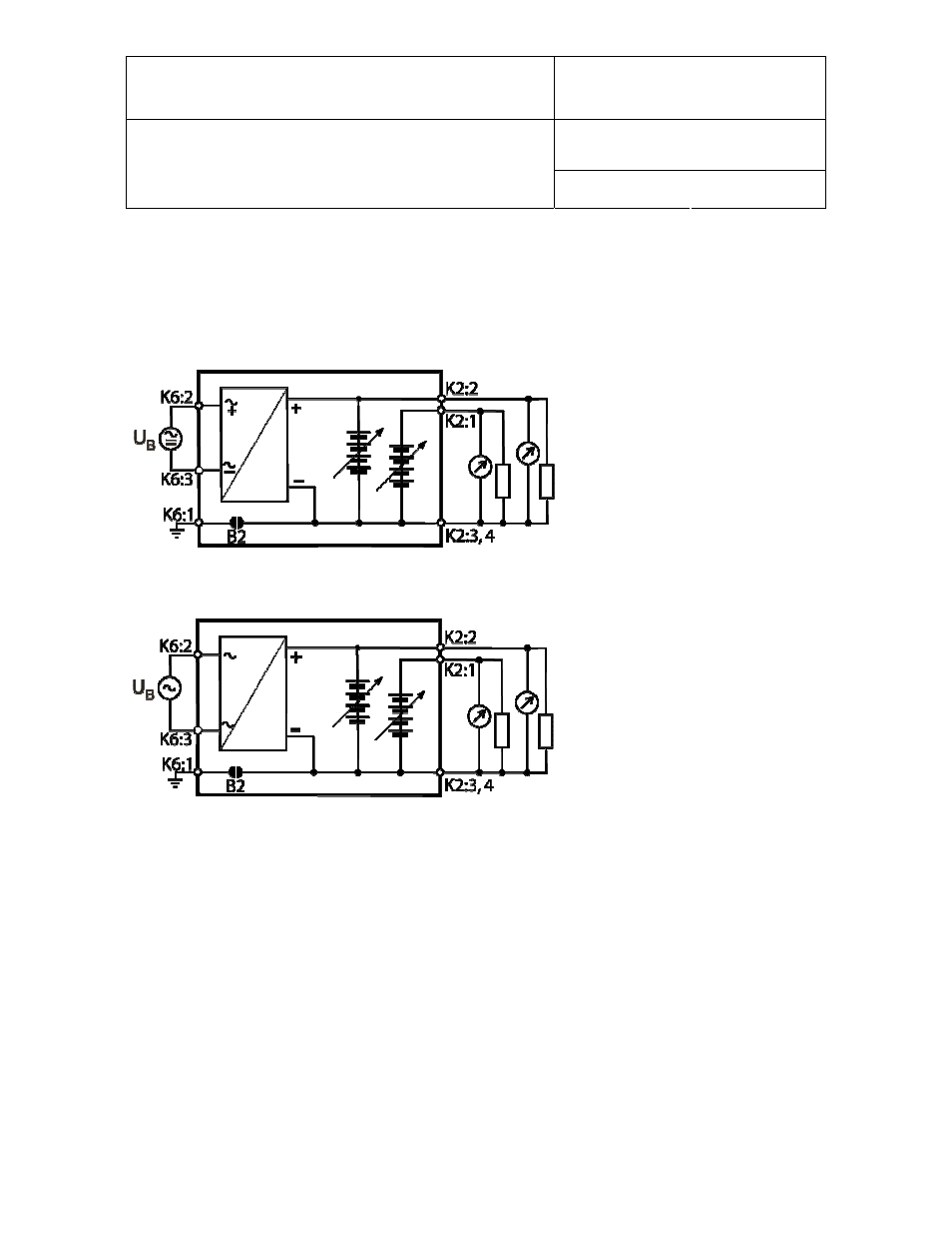
HF631 to HF63A: 3-wire analog transmitter
Electrical diagram 15 to 40 VDC or 12 to 28 VAC power supply with voltage outputs
Electrical diagram 85 to 265 VAC power supply with voltage outputs
The maximum permissible cable length can be determined under consideration of the voltage drop caused by
the current flowing to the devices connected to the unit. The voltage drop in the cable depends both on cable
resistance and on the equivalent resistance of the devices connected in parallel to the unit. The total
resistance connected to each unit output should be at least 1000 ohms. Cable resistance should not be more
than 1/1000 of the load resistance.