ROTRONIC Lan interface User Manual
Lan-interface-(us)
Reset
Ethernet
5 V
4 3 2 1
LED
HF
Reset
Ethernet
5 V
4 3 2 1
LED
HF
12
.8
000
.2
003
12
.8
000
.2
003
ROTRONIC AG, CH-8303 Bassersdorf
Tel. +41 44 838 11 44, www.rotronic.com
ROTRONIC Messgeräte GmbH, D-76275 Ettlingen
Tel. +49 7243 383 250, www.rotronic.de
ROTRONIC SARL, 56, F - 77183 Croissy Beaubourg
Tél. +33 1 60 95 07 10, www.rotronic.fr
ROTRONIC Italia srl
,
I- 20157 Milano
Tel. +39 2 39 00 71 90, www.rotronic.it
ROTRONIC Instruments (UK) Ltd, West Sussex, RH10 9EE
Phone +44 1293 571000, www.rotronic.co.uk
ROTRONIC Instrument Corp, NY 11788, USA
Phone +1 631 427-3898, www.rotronic-usa.com
ROTRONIC South East Asia Pte Ltd, Singapore 339156
Phone +65 6294 6065, www.rotronic.com.sg
ROTRONIC Shanghai Rep. Office, Shanghai 200233, China
Phone +86 40 08162018, www.rotronic.cn
Herzlichen Glückwunsch zum Kauf Ihres neuen LAN-Interfaces. Sie haben damit ein dem neuesten
Stand der Technik entsprechendes Gerät erworben. Bitte lesen Sie diese Kurzanleitung genau
durch, bevor Sie das Gerät installieren.
Best.-Nr.
Gerätetyp
LAN-INTERFACE
LAN Interface 433,92 MHz Version
LAN-INTERFACE-US LAN Interface 915 MHz USA Version
Allgemeine Beschreibung
Das LAN-Interface ermöglicht unter Verwendung einer Ethernet-Infrastruktur die Kommunikation
mit drahtlosen Geräten über eine grössere Entfernung hinweg. Die Platzierung mehrer Interfaces
an unterschiedlichen Standorten ermöglicht den Zugriff auf räumlich verteilte Endgeräte von
einem zentralen Ort aus. Diese Kurzanleitung behandelt die Standortwahl, Aufstellung und den
Anschluss des Interfaces.
Hinweise zur Nutzung
Zur Nutzung des LAN-Interfaces wird eine konfigurierte Ethernet-Infrastruktur mit 100MBit Über-
tragungsrate benötigt. Das Gerät ermöglicht im Zusammenspiel mit der HW4-Software die Kommu-
nikation mit geeigneten Funkgeräten. Zur Konfiguration der Ethernet-Parameter des LAN-Interface
wird ein PC mit HW4 oder einem gängigen Webbrowser (z.B. Firefox, InternetExplorer) benötigt,
welcher in die gleiche Ethernet-Infrastruktur eingebunden ist. Das LAN-Interface und das mitge-
lieferte Steckernetzteil sind ausschliesslich für die Verwendung im Innenraumbereich ausgelegt.
Geräteansicht und Standardkonfiguration
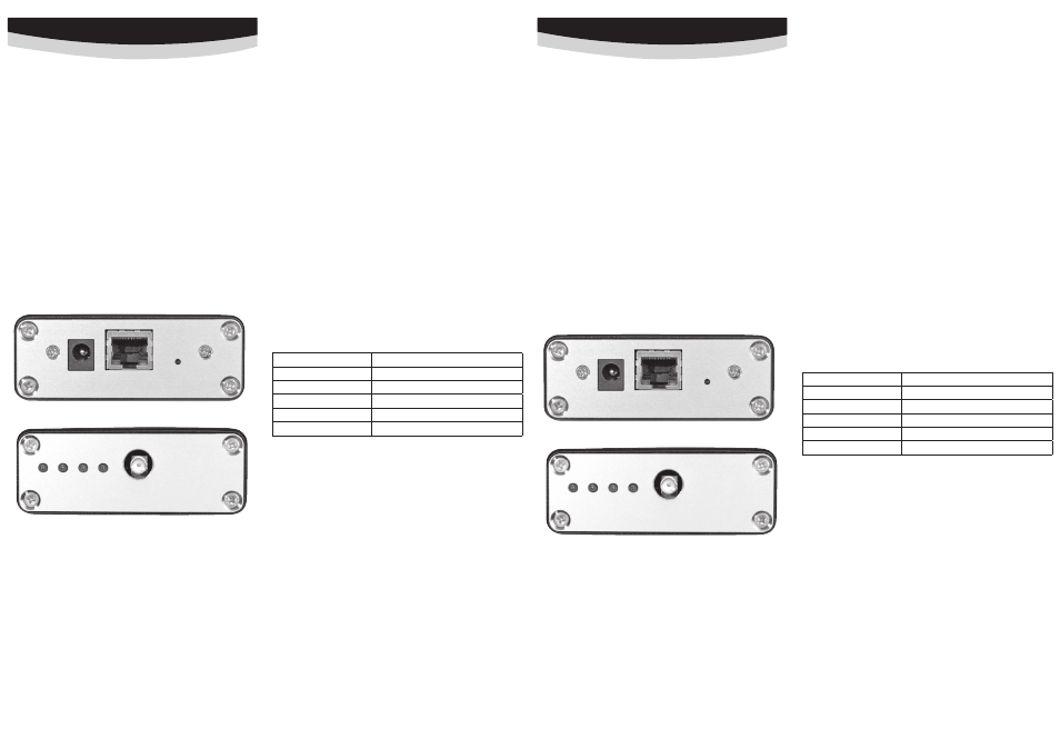
Anschlüsse und LED’s:
5V Netzteilanschluss
Ethernet
RJ45-Netzwerkanschluss
Reset
Drucktaster zum Zurücksetzen der Netzwerkkonfiguration in den
Auslieferungszustand.
HF Antennenanschluss
LED1 Spannungsversorgung
LED2
Funkdaten werden gesendet (blitzend)
LED3
Empfangene Funkdaten werden verarbeitet (blitzend)
LED4
Status, blinkend in folgenden variablen Intervallen (s.u.)
Das LAN-Interface ist bei Auslieferung mit folgenden Netzwerkeinstellungen konfiguriert:
IP
192.168.1.120
Netmask
255.255.255.0
Gateway
192.168.1.1
DNS 192.168.1.1
Netzwerkname rotroniclan
DHCP an
KURzBEDIENUNGSANLEITUNG
Standortwahl
Für eine optimale Sende- und Empfangsreichweite ist der Standort in trockenen Innenräumen
nach folgenden Kriterien zu wählen:
• Waagerecht, frei zugänglich (nicht durch Gegenstände verstellt)
• Keine metallischen Gegenstände (Wasserleitungen, Stahlschränke, o.ä.)
• Idealerweise besteht eine «Sichtverbindung» zwischen Antenne und anzusprechendem Gerät
• Sonneneinstrahlung, Feuchtigkeit und Temperaturwechsel vermeiden
Anschluss
Stabantenne im Uhrzeigersinn auf den goldfarbenen HF-Anschluss aufschrauben. Die Montage
der Antenne erfolgt ausschliesslich über die Überwurfmutter. Das Gerät mit einem geeigneten
Patchkabel über die Ethernet-Buchse mit der Netzwerkinfrastruktur verbinden. Den Klinkenstecker
des Netzteils mit der 5V-Buchse des Gerätes verbinden.
Hinweis: Bei Änderungen am Antennen- oder Netzwerkanschluss ist das Gerät vorher vom
Stromnetz zu trennen!
Reset: Drucktaster zum Zurücksetzen der Netzwerkkonfiguration in den Auslieferungszustand.
Erste Inbetriebnahme:
Nachdem das Gerät zum ersten Mal mit dem Stromnetz verbunden wurde, leuchtet LED1 auf
und das LAN-Interface durchläuft die folgende Startphase, deren Status durch LED4 gezeigt wird:
25ms:
Netzwerkkonfiguration wird per DHCP abgefragt.
100ms:
DHCP-Anfrage Fehlgeschlagen, keine benutzerdefinierten Einstellungen vorhanden.
Die Netzwerkschnittstelle wurde automatisch mit den Werten bei Auslieferungs-
zustand konfiguriert
1s:
Netzwerkkonfiguration wurde erfolgreich vom DHCP-Server bezogen.
2s:
Benutzerdefinierte Netzwerkkonfiguration (DHCP-Nutzung deaktiviert).
Die Netzwerkkonfiguration sollte nun über das Webinterface oder die HW4-Software (siehe auch Do-
kumentation der HW4) angepasst und individualisiert werden. (weiter Informationen s. Anleitung
)
Verwendete Ports
Beim Betrieb des LAN-Interfaces in einem Firmennetzwerk müssen folgende Ports auf der Firewall
offen sein:
– TCP 6767 (Kommunikation mit HW4 und LAN-Interface)
– TCP 3384 (Suche des LAN-Interface)
– UDP 67, 68, 69, 9 (Firmware update LAN-Interface)
Technische Daten:
Gehäuse
Aluminium, Schutzart IP20
Antennenanschluss
HF via 50
Ω SMA-Stecker
Einsatzbereich
-20 bis +85 °C, max. 90% Luftfeuchte
Netzwerkanschluss
Fast Ethernet (10/100MBit) via RJ45-Stecker
Stromversorgung
5VDC Klinkenstecker
Stromaufnahme
Max. 200 mA
LAN-INterfAce-(US)
Congratulations on your purchase of the new state-of-the-art LAN-Interfae. Please read these short
instructions carefully before installing the device.
Order Code
Device type
LAN-INTERFACE
LAN Interface 433,92 MHz Version
LAN-INTERFACE-US LAN Interface 915 MHz USA Version
General description
The LAN interface communicates with wireless devices over a greater distance by using an Ether-
net infrastructure. The placement of multiple interfaces in different locations provides access to
spatially distributed devices from a central location. This quick reference guide is limited to the
description of the main features and the installation of the device.
Handling
The LAN interface requires a configured Ethernet infrastructure with a transfer rate of 100MBit.
The device enables the interaction with the HW4 software to communicate with appropriate
radio equipment. To configure the Ethernet parameters of the LAN interface, a PC with HW4 or a
standard Web browser (eg Firefox, Internet Explorer) which is integrated into the same Ethernet
infrastructure is required. The LAN interface and the included AC adapter designed exclusively
for use in interior areas.
Device View and Standard Configuration
Connectors and LED’s
5V
Power supply connector
Ethernet
RJ45- Network Connection
Reset
Push button to reset the network configuration to factory default.
HF
Antenna connection
LED1
Power supply
LED2
Radio data is sent (blinking)
LED3
Received radio data is processed (blinking)
LED4
Status, blinking in the following variable intervals (see below)
The LAN interface is configured upon delivery with the following network settings
IP
192.168.1.120
Netmask
255.255.255.0
Gateway 192.168.1.1
DNS 192.168.1.1
Network name rotroniclan
DHCP on
SHORT INSTRUCTION mANUAL
Choice of location:
For optimal transmission and reception range the interior site of placement has to meet the fol-
lowing criteria:
• Horizontal, freely accessible (not blocked by objects).
• Do not place close to metallic objects (water pipes, steel cabinets, etc.).
• Ideally, there is a “visual connection” between the antenna and the device.
• Avoid direct sunlight, moisture and temperature changes.
Connection
Screw the antenna clockwise to the gold colored RF connector. Mount he antenna only by turning the
nut. Connect the device via the Ethernet port to the network infrastructure by using an appropriate
patch cable. Connect the AC adapter to the mains and the 5V jack of the device.
Note: Prior to changes of the antenna or network connection, the device has to be separated
from the mains!
Reset: Push button to reset the network configuration to its factory defaults.
Initial Setup
After the device is connected for the first time the mains LED1 starts flashing. The LAN-Interface
now follows the below start-up-sequence, shown by LED4:
25ms:
Network configuration is queried via DHCP.
100ms:
DHCP request failed, no custom settings available. The network interface is
automatically configured with factory settings
1s:
Network configuration was successfully obtained from the DHCP server.
2s:
Custom network configuration (DHCP disabled).
Now the network configuration should be customized by using HW4 software (further information
see manual).
Ports used
During operation of the LAN interfaces in a corporate network, the following ports must be open
on the firewall:
– TCP 6767 (communication with HW4 and LAN-INTERFACE)
– TCP 3384 (search of the LAN-INTERFACE)
– UDP 67, 68, 69, 9 (firmware update LAN-INTERFACE)
Technical Specifications:
Housing
Alu, protection class IP20
Antenna connector
HF via 50
Ω SMA-connector
Range of use
-20 to +85 °C, max. 90% air humidity
Network Connection
Fast Ethernet (10/100MBit) via RJ45 connector
Power Supply
5VDC jack connector
Current consumption
Max. 200 mA
LAN-INterfAce-(US)