Dwyer ULTM User Manual
Page 5
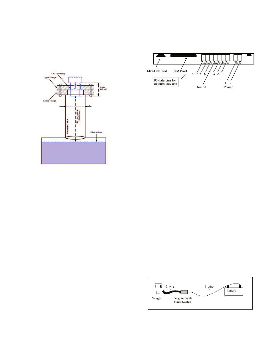
A typical structure of an extension pipe is shown in Figure 6 below. Closely follow
these guidelines when using an extension pipe:
• Internal pipe diameter should be at least 3˝ (7.62 cm) wide.
• The diameter of the hole on the flange or tank should not be smaller than the pipe
diameter.
• Pipe length (measured from sensor face) should be no longer than 20˝ (50 cm).
• The pipe should not protrude into the tank.
• Pipe should be exactly perpendicular to the surface of the target.
• Sensor must be located at the center of the pipe.
• Pipe should have a smooth interior surface.
• The hole in the flange or tank should have a smooth edge and welding spots must
be avoided.
5. Temperature Considerations and Temperature Sensors
Also refer to Chapter 8 reference guide: “Temperature Sensors, Units and Display”
(p.17).
When using an external temperature sensor, place the sensor at a location that
best represents temperature of the air between the sensor face and the target.
Connect the sensor internally as described in the electrical connection section to
the Thermistor pins. External temperature sensors may be ordered from the
manufacturer or may be purchased independently. Use Thermistor NTC 10 K Ω 5%
(minimum), ULTM-EXT or equivalent.
When using the internal temperature sensor, avoid situations where the Series
ULTM is exposed to different thermal conditions other than its environment, such
as direct sunlight. Direct sunlight may overheat the system and cause
measurement inaccuracies, measurement variations in time, and even failure of the
system in extreme cases. If the Series ULTM is exposed to direct sunlight,
construct a local sunshade (“umbrella”) over the ULTM.
In areas of large temperature variations, take into consideration volume changes of
the target due to temperature expansion.
6. Electrical Connections
Carefully follow these steps when connecting a power supply to the Series ULTM.
Power supply must fulfill the proper rating requirements as defined in the
specifications chapter above.
6.1 Turn off Series ULTM.
6.2 Turn the ULTM top cap counter-clockwise and expose the electrical
connections board. Identify the elements as shown in the following figure.
6.3 Insert power cables into the Series ULTM through one of the glands.
Ensure that high voltage sources or cables are at least 3.28´ (1 m) away from
Series ULTM and cables.
Keep the electrical supply lines away from electromagnetic interference
sources.
When inserting a cable through the gland, use round cables with a minimum
diameter of 0.24˝ (6 mm) to ensure that the unit remains sealed to IP67 rating.
Connector terminals may be pulled up for easy wire connection and then re-
inserted back again.
6.4 Connect the power cables to the appropriate terminals.
Note: The Series ULTM operates from a DC power supply of 8 to 33 VDC.
Always make sure that sufficient voltage is present on the Series ULTM power
terminals, disregarding of any voltage drop along the supply lines.
6.5 When using an external temperature sensor or ULTM-EXT, connect the
thermistor to data pins 6 and 7. *Do not wire ULTM-PTS and ULTM-EXT at the
same time.
6.6 When using an external Programmable Timer Switch ULTM-PTS, connect the
switch to pins 6 and 7.
6.7 When using a contact alert, connect short/open between pins 5 and 4 (ground).
See the section about contact alerts in the Chapter 8 reference guide.
6.8 The mini-USB port is a USB device-side supporting virtual COM ports. The port
may be used for firmware upgrades, field monitoring and remote setup. Details
about firmware upgrade are provided in the Chapter 5: Firmware Updates
(p.12).
7. Low Power Mode and Programmable/Timer Switch (PTS), ULTM-PTS
Series ULTM supports low power mode for extended external battery lifetime. This
mode of operation requires the external Programmable Timer Switch (PTS) ULTM-
PTS to be connected between Series ULTM and battery.
PTS connections:
• First connect the 5-wire cable from the ULTM-PTS to Series ULTM through one
of the glands.
• Connect the Brown (+) wire to the power plus (+) on Series ULTM.
• Connect the Yellow (-) wire to the power minus (-) on Series ULTM.
• Connect the White wire to pin 6 on the electrical port panel (see Figure 7
above).
• Connect the Green wire to pin 7 on the electrical port panel.
• Connect the Blue (ground) wire to the ground port on Series ULTM.
• Then connect the 3-wire cable from the ULTM-PTS to the battery.
• Connect the Brown (+) wire to the battery plus (+).
• Connect the Yellow (-) wire to the battery minus (-).
• Connect the Blue wire to a local ground at or nearby the battery.
See PTS software configuration in Chapter 8: Reference Guide.
Page 4
Figure 6: Possible Extension Pipe Fittings.
Figure 7: Electrical Connections.
*GROUND (Pin 4) is a ground and not a common.
*Pins 1-3 are not used on this device.
Figure 8: Programmable Timer Switch Connections.
ULTM