Dwyer ULTM User Manual
Page 17
Selecting feet as your distance unit implies the Imperial (US / English) unit system.
Distance units can only be modified with the PC configuration tool using the
command: UNT.
ULTM built-in display may be configured to display different variables. Distance and
level may always be selected as the variable to be displayed. When tank shape and
dimensions are defined, ULTM may also be set to display volume of the target.
Volume display may be turned on with the PC configuration tool using the VAL
command. Distance or level may be set from the keypad or from the PC
configuration tool.
False Echo Scan
False echo scan is a procedure for identifying and extracting fixed obstructions
nearby the target or sensor. This procedure should be performed when the tank is
empty. This procedure is initiated from the keypad only. Further information is
provided in the Chapter 3 describing configuration with a keypad/display under the
basic setup option.
Filling Rate
Filling rate allows you to tune the tracking of ULTM to fast moving targets. You
should increase the filling rate figure if your target fills up or drains down rapidly.
Always use the lowest possible filling rate in order to preserve accuracy of the
measurement. A high filling rate will allow better tracking before lost of echo when
the target moves rapidly. For nearby full (empty) levels, the tracking rate is reduced
to avoid erratic entry into full (empty) level.
Full and Empty Alerts
You may activate or deactivate full and empty SMS alerts. Full and empty alerts
co-exist with periodic alerts. A three-minute quiet interval is maintained between
two alerts. Within this quiet interval time, no SMS alerts will be sent.
GSM Display Status Reports
The following status reports may be presented (or shown) on the display:
The Sequence of Status Reports is as Follows:
When ULTM is turned ON, it first searches for a proper level target. Once found,
ULTM begins to seek for a ULTM network. A status report GSM INITIALIZING will
be displayed at this time. The search for GSM network may take between 10
seconds and up to a minute.
If ULTM fails to locate a GSM network, one of the error indications will be displayed.
When such an error occurs, verify by using a cell-phone that the area is indeed
covered by a GSM network and that the SIM card you inserted into the ULTM is
good. Let ULTM do some retries for 30 seconds and then turn ULTM OFF and then
ON again to try again.
If ULTM successfully locates a GSM network, the status report GSM PERIODIC
ACTIVE will be displayed. When an SMS is transmitted, a sequence of status
reports will show: GSM DESTINATION ASSIGNED, GSM SMS SENT, and GSM
PERIODIC ACTIVE. GSM EVENTS ONLY report is displayed if the user disabled
periodic SMS reports. Disabling the periodic SMS report is performed by entering
0 (zero) at the report interval, either manually or by using the PC configuration
command SMST.
ULTM Reporting Interval
You can determine the periodic reporting interval using one of the configuration
methods. The interval is defined in seconds. For example, for an SMS report once
every hour, modify the interval to 3600. Report intervals lower than 180 seconds
are not accepted and will revert to 180 seconds. Maximum report interval is
3,999,999 seconds, which comes up to about 45 days. A reporting interval of 0
(zero) disables the periodic reports.
Interdependencies
For Metric Units
For American Units
PTS Configuration
The Programmable Timer Switch (ULTM-PTS) is an external device for enabling
low power mode of ULTM.
The PTS turns ULTM ON to take a measurement and to transmit the measured
information. Then the PTS turns ULTM OFF for a sleeping period. ULTM is then
turned ON again and so on. With this method, a 20 AH/12 V battery can typically
feed ULTM for 1 to 3 years before replacement is needed.
Two different sleeping intervals may be programmed by the user: long interval and
short interval.
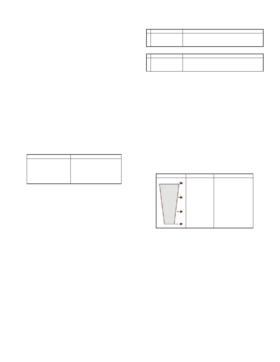
The sleeping interval in-effect depends on the level being measured. For example,
assume that a river overflows at a level of 6.6´ (2.0 meters) and calm waters are
defined at a level of 3.28´ (1.0 meter). Then you can define a very long sleeping
interval (e.g. 6 hours) when level measurement is between 0 and 3.28´ (0 to 1.0
meters). You can further define a short interval of 30 minutes when the level is
between 3.28´ (1.0 meter) and 5.98´ (1.8 meters). Finally, above 5.9´ (1.8 meters)
the PTS may be disabled and ULTM will operate continuously.
When operating continuously, the period between messages is defined by the
ULTM reporting interval parameter.
This concept is further described in the following figure:
PTS parameters are defined by the command LPST as described in the Chapter 4
“Configuration with a PC”. Both sleep intervals must be longer than 10 minutes. The
SMS messages during the long sleep interval may be cancelled. Do not configure
ULTM while the system is connected to a battery through the PTS. A shutdown may
be forced by the PTS causing loss of data.
Refill Alerts
When refill alerts are activated, ULTM identifies a refilling process. ULTM transmits
an SMS soon after the refilling is identified and a second SMS soon after the
refilling process has ended. The first SMS provides distance information (distance
between sensor and fuel surface). The second SMS provides information about the
filling quantity. This procedure allows more accurate refilling information when
compared with the information that can be extracted from periodic reports.
Reset and Operating Hours
ULTM may be reset to their factory defaults. This operation may be performed from
the keypad or from the PC configuration tool (command RSD). Once executed, the
ULTM will return to the state as delivered from the factory. ULTM may also be reset
to restart without any change in the pre-configured parameters (command RST).
ULTM keeps track of two counters for measuring operating hours.
• Non resettable counter (Odometer principle)
• Resettable counter (Trip-meter principle)
Page 16
Error Indications
GSM REGISTRATION FAIL
GSM MODEM NOT READY
GSM TRANSMISSION FAIL
GSM SIM FAIL
GSM NOT ACTIVE
Proper Operation
GSM INITIALIZING
GSM REGISTRATION SENT
GSM ACTIVE
GSM DESTINATION ASSIGNED
GSM SMS SENT
GSM EVENTS ONLY
Applicable to items
EMP, FUL,NBD, FBD
VAL=3,6
Interdependencies
0.15 ≤ NBD ≤ FUL ≤ EMP ≤ FBD ≤ 8.000
One and only one of the following must be configured:
CUB, CYLH, CYLV
1
2
Applicable to items
EMP, FUL,NBD, FBD
VAL=3,6
Interdependencies
0.50 ≤ NBD ≤ FUL ≤ EMP ≤ FBD ≤ 26.00
One and only one of the following must be configured:
CUB, CYLH, CYLV
1
2
Predefined levels
Full Level
High Level
Low Level
Empty Level
Standby modes
Continuous measurement
Short sleep intervals
Long sleep intervals
Vessel
Figure 18: Low Power Predefined Levels.