General safety information, Installation, Electrical – Blue Angel Pumps SBS50BOOST User Manual
Page 2: Continued), Sbs50 boost
2
Risk of electrical
shock. This pump is
designed for indoor installation only.
All wiring should
be performed by a
licensed or certifi ed electrician.
10. For safety, the unit must be
connected to a grounded circuit
equipped with a ground fault
interrupter device.
11. Before installing the pump, have the
electrical outlet checked by a licensed
or certifi ed electrician to make sure
the outlet is properly grounded.
12. Make sure the line voltage and
frequency of electrical current supply
agrees with the motor wiring.
Do not attempt to
use product at 240
volt. Only 120 volt is allowed.
13. Do not attempt repairs to the electric
motor. All repairs to the motor
must be completed at a licensed or
certifi ed electrical motor repair shop.
Do not touch an
operating motor.
Modern motors are designed to operate
at high temperatures.
14. Avoid kinking electrical cord and protect
from sharp objects, hot surfaces, oil and
chemicals. Replace or repair damaged or
worn cords immediately.
Disconnect power and release all
pressure from the system before
attempting to install, service, relocate
or perform any maintenance. Lock the
power disconnect in the open position.
Tag the power disconnect to prevent
unexpected application of power.
15. Keep
fi ngers and foreign objects away
from ventilation and other openings. Do
not insert any objects into the motor.
Risk of electric shock!
Never connect the
green (or green and yellow wire) to a
live terminal!
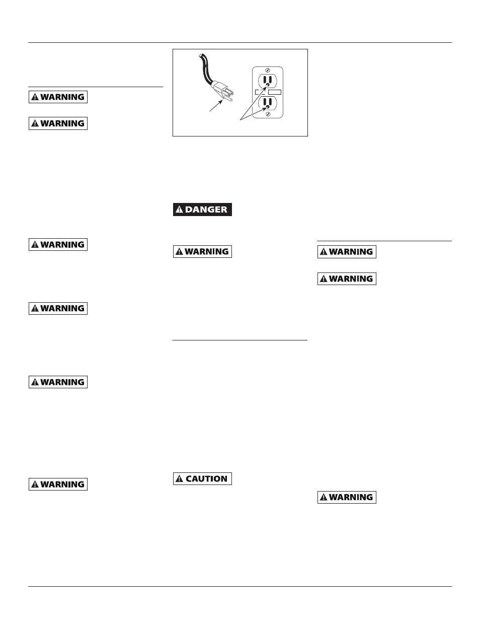
16. To reduce the risk of electrical shock,
the pump should be plugged directly
into a properly installed and grounded
3-prong grounding type receptacle, as
shown in Figure 2. The green (or green
and yellow) conductor in the cord is
the grounding wire. The motor must
be securely and adequately grounded
for protection against shock.
General Safety
Information
(Continued)
17. Where a 2-prong is encountered,
replace the plug with a properly
grounded 3-prong receptacle in
accordance with the National Electrical
Code, local codes and ordinances.
To ensure a proper ground, the
grounding means must be tested by a
licensed or certifi ed electrician.
Do not handle pump
or pump motor with
wet hands, when standing on a wet or
damp surface or when standing in water.
Fatal electrical shock could occur.
Pump motor is
equipped with an
automatic resetting thermal protector
and may restart unexpectedly. Protector
tripping is an indication of motor
overloading because of operating pump
at low heads (low discharge restriction),
excessively high or low voltage,
inadequate wiring, incorrect motor
connections or defective motor or pump.
Installation
LOCATION
Select a location as close to the water supply
as possible. Be sure to comply with any state
or local codes regarding the placement
of the pump. The equipment must be
protected from the elements. A basement
or heated pump house is a good location.
Make sure the pump has proper ventilation.
The temperature surrounding the pump
is not to exceed 100°F (40°C) or nuisance
tripping of the motor overload may occur.
PIPING
Piping may be copper, steel, rigid PVC
plastic or fl exible polyethylene plastic.
Flexible pipe is not
recommended on
suction pipe (inlet pipe). Flow sensor is
designed for 1” NPT connection.
The pipe must be clean and free of rust or
scale. Apply Tefl on
®
thread tape or sealant
to the 1” male NPT pipe threads and install
the switch into the piping system. Thread the
fl ow switch onto the male pipe thread until
hand-tight. Tighten pipe 1 additional turn. If
improper seal results, continue turning pipe
into unit 1/4 turn increments. Do Not Exceed
1 Additional Turn All connections must be air
tight to insure normal operation.
TEST
RESET
Grounded
Pin
Grounded Outlet
Figure 2
Slope all inlet piping upwards towards
the pump to prevent trapping air.
IMPORTANT: Pump is built to handle
clear water only; it is not designed to
handle water containing sand, silt or
other abrasives.
1. Refer to Figure 3 for typical
installations.
2. Bolt pressure booster system to a
secure foundation.
3. Locate the pump so that there will
always be a positive supply of water
to the pump (See Figure 3).
4. For service convenience, the installer
is recommended to add gate valves
and unions as needed to provide for
easier maintenance.
5. Pressure gauges on the inlet and
outlet, provided by the installer, are
recommended to show if suffi cient
water is being supplied to the pump
and to show service pressure.
Electrical
Risk of electrical
shock. This pump is
designed for indoor installation only.
Disconnect power
and release all pressure from the system
before attempting to install, service,
relocate or perform any maintenance.
IMPORTANT: Do not use an extension
cord or splice wires. Joints should be
made in an approved junction box. If the
above information is confusing, consult
a licensed electrician.
Your unit is supplied with a pressure
switch, fl ow sensor and a control box.
The only wire connection needed is to
plug the two red wires from the control
box into the two red wires on the fl ow
sensor (See Figure 3).
MOTOR PROTECTION
This motor has built in thermal protection.
The overload protects the motor against
burnout from overload of low voltage,
high voltage and other causes. The device
is automatic and resets itself once the
temperature has dropped to a safe point.
Frequent tripping of the device indicates
trouble in the motor or power lines and
immediate attention is needed.
Never
examine,
make wiring changes
or touch the motor before disconnect-
ing the main electrical supply switch.
The thermal device may have opened the
electrical circuit. The pump motor should
be equipped with a correctly fused discon-
nect switch to provide protection. Consult
local or United States National Electrical
Codes for proper fuse protection.
www.blueangelpumps.com
Operating Instructions and Parts Manual
SBS50 Boost