Alarm operation 4.2 – West Control Solutions MRC 8000 User Manual
Page 43
43
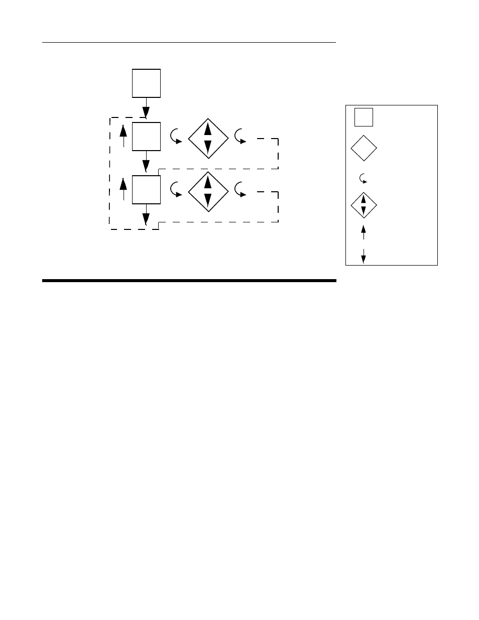
STANDBY MODE FLOW CHART (APPLIES TO RECORDING CONTROLLERS)
Alarm Operation 4.2
There are two alarms available per pen. The type of alarm is selected in the Program mode
as follows:
1. Process Alarm Direct - the alarm will be On if the process value is greater than the process
value selected.
2. Process Alarm Reverse - the alarm will be On if the process value is less than the process
value selected.
3. Deviation Alarm Direct* - the alarm will be On if the process value is greater than the
setpoint plus the deviation value selected.
4. Deviation Alarm Reverse* - the alarm will be On if the process value is less than the
setpoint plus the deviation value selected.
5. Deviation Band Alarm Open Within* - the alarm will be On if the process value is greater
than one half the deviation band alarm values selected above or below the setpoint.
6. Deviation Band Alarm Close Within* - the alarm will be On if the process value is less than
one half the deviation band value selected above or below the setpoint.
* Applies to Recording Controllers
The alarms will be active while the instrument is in the Operation mode (Recorder) or Control
mode (Recording Controller). Relay and solid state relay drivers can be assigned to provide
output capability for the alarm functions.
The alarm value (Process, deviation, or bandwidth) is selected in the Alarm Set mode
(Recorder) or Tune mode (Recording Controller).
Alarm outputs chatter can be reduced by using the hysteresis for the alarm output adjustable
in the Program mode to create a deadband around the alarm point.
Po2
Po1
Stby
ON
OFF
Actual Display
On/Off Display -
Use arrow keys
to turn on or off
Scroll Key
Numeric Display -
Use arrow keys
to change value
Up Arrow Key
Down Arrow
KEY