West Control Solutions MRC 8000 User Manual
Page 11
11
contact with each other and amount of cross talk. Cross talk is due to the EMF (Electro
Magnetic Flux) emitted by a wire as current passes through it.
2.5.1.4 USE OF SHIELDED CABLE
Shielded cable helps eliminate electrical noise being induced on the wires. All analog signals
should be run with shielded cable. Connection lead length should be kept as short as pos-
sible, keeping the wires protected by the shielding. The shield should be grounded at one end
only. The preferred grounding location is at the sensor, transmitter or transducer.
2.5.1.5 NOISE SUPPRESSION AT THE SOURCE
Usually when good wiring practices are followed, no further noise protection is necessary.
Sometimes in severe environments, the amount of noise is so great that it has to be sup-
pressed at the source. Many manufacturers of relays, contactors, etc. supply "surge suppres-
sors" which mount on the noise source.
For those devices that do not have surge suppressors supplied, RC (resistance-capacitance)
networks and/or MOV (metal oxide varistors) may be added.
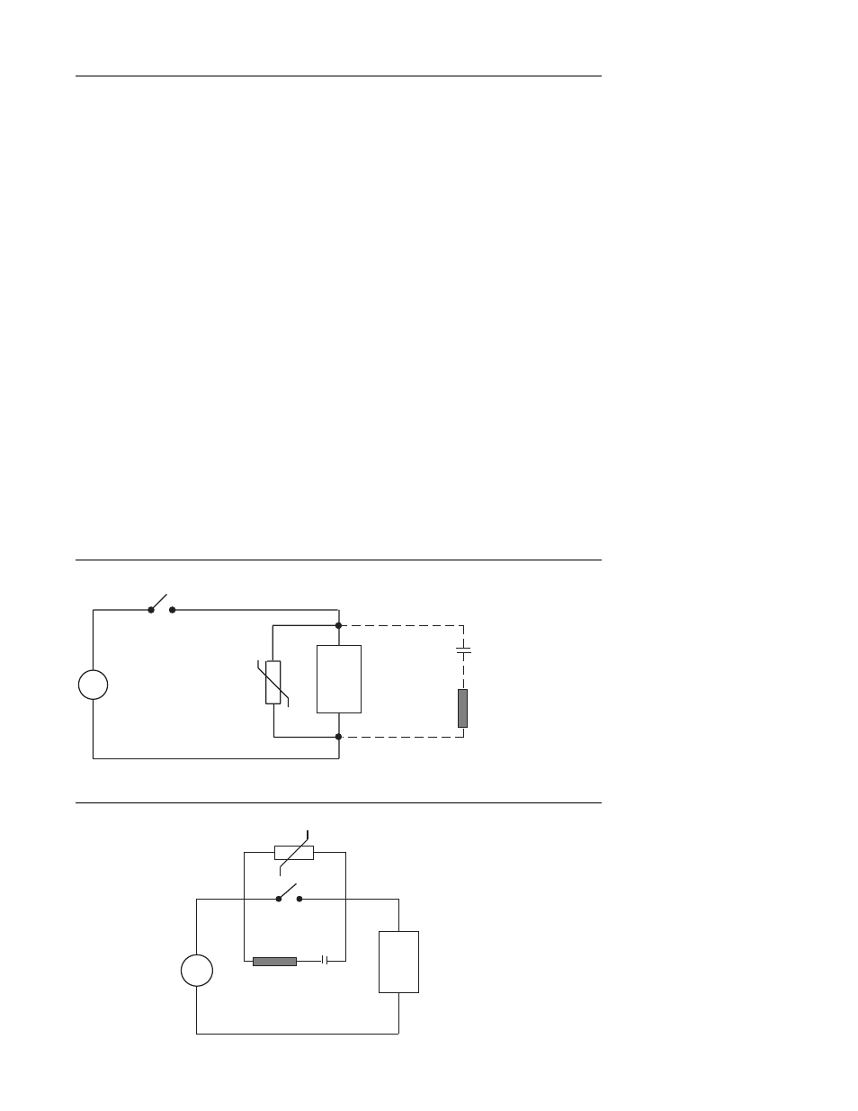
Inductive Coils - MOV's are recommended for transient suppression in inductive soils con-
nected in parallel and as close as possible to the coil. See Figure 2-2. Additional protection
may be provided by adding an RC network across the MOV.
Contacts - Arcing may occur across contacts when the contact opens and closes. This results
in electrical noise as well as damage to the contacts. Connecting a RC network properly
sized can eliminate this arc.
For circuits up to 3 amps, a combination of a 47 ohm resistor and 0.1 microfarad capacitor
(1000 volts) is recommended. For circuits from 3 to 5 amps, connect 2 of these in parallel.
See Figure 2-3.
FIGURE 2-2
FIGURE 2-3
A.C.
MOV
Inductive
Load
C
R
0.5
mfd
1000V
220
ohms
115V 1/4W
230V 1W
A.C.
MOV
R
Inductive
Load
C