20 configuration 3.1, Mode display code function description – West Control Solutions MRC 8000 User Manual
Page 20
20
Configuration 3.1
After completing installation and wiring of the instrument the configuration (set up) procedures
must be performed to prepare the instrument for operation on the intended application. The
procedures include selecting specific parameters, entering data and possible jumper position-
ing. Once properly configured the instrument will retain the user selections in memory so this
procedure need not be repeated unless required by changes in the application.
Parameter selections and data entry are made via the front keypad. To ease configuration
and operation, user entered data has been divided up into several sections referred to as
modes. Each mode contains a different type of data or may be used for specific operating
functions. For two pen instruments, some modes are common to both pens. These modes are
as follows:
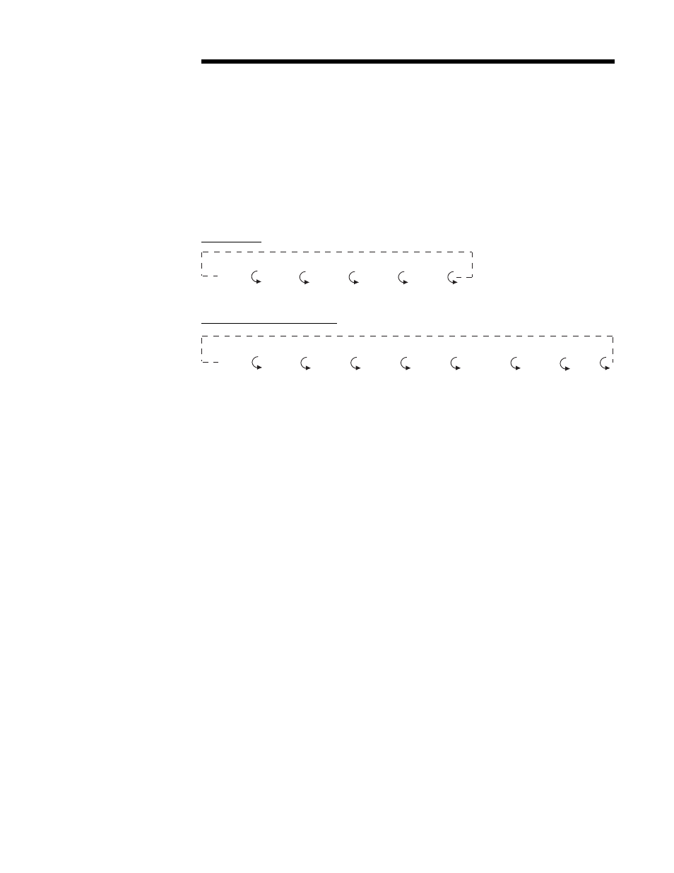
RECORDER-
RECORDING CONTROLLER-
MODE
DISPLAY CODE
FUNCTION
DESCRIPTION
Off
oFF
Operation
Outputs and Alarms
are Off
Chart may stop
rotating(selectable)
Operate* oPEr Operation
Limits and Alarms
are Active
Control**
CtrL
Control
Outputs and Alarms
are Active
Test
tESt
Service
Tests Instrument
Operation
Calibration
CAL
Service
Calibrates, Resets
Instrument
Program
Prog
Configuration
Configure Operating
Parameters
Alarm Set* ASEt Configuration &
Enter Alarm Settings
Operation
Tune**
tunE
Configuration &
Enter Tune and
Operation
Alarm Settings
Setpoint Selection**
SPS
Operation
Selects Remote or
Local Setpoint
Operation (Remote
Setpoint Optional)
* Applies to Recorders
** Applies to Recording Controllers
Operation
(oPEr)
Test
(tESt)
Program
(Prog)
Alarm Set
(ASEt)
Calibrate
(CAL)
Control
(CtrL)
Test
(tESt)
Program
(Prog)
Tune
(tunE)
Setpoint Select
(SPS)
Calibrate
(CAL)
Standby
(Stby)
OFF
(oFF)