2 electrical connections 7, 1 connecting diagram 7, Connecting diagram 7 – West Control Solutions N8800 User Manual
Page 7: 2 terminal connection, 2 out1/2 heating/cooling, 5 inp2 current tansformer
2.2 Terminal connection
Power supply connection 1
See chapter 10 "Technical data"
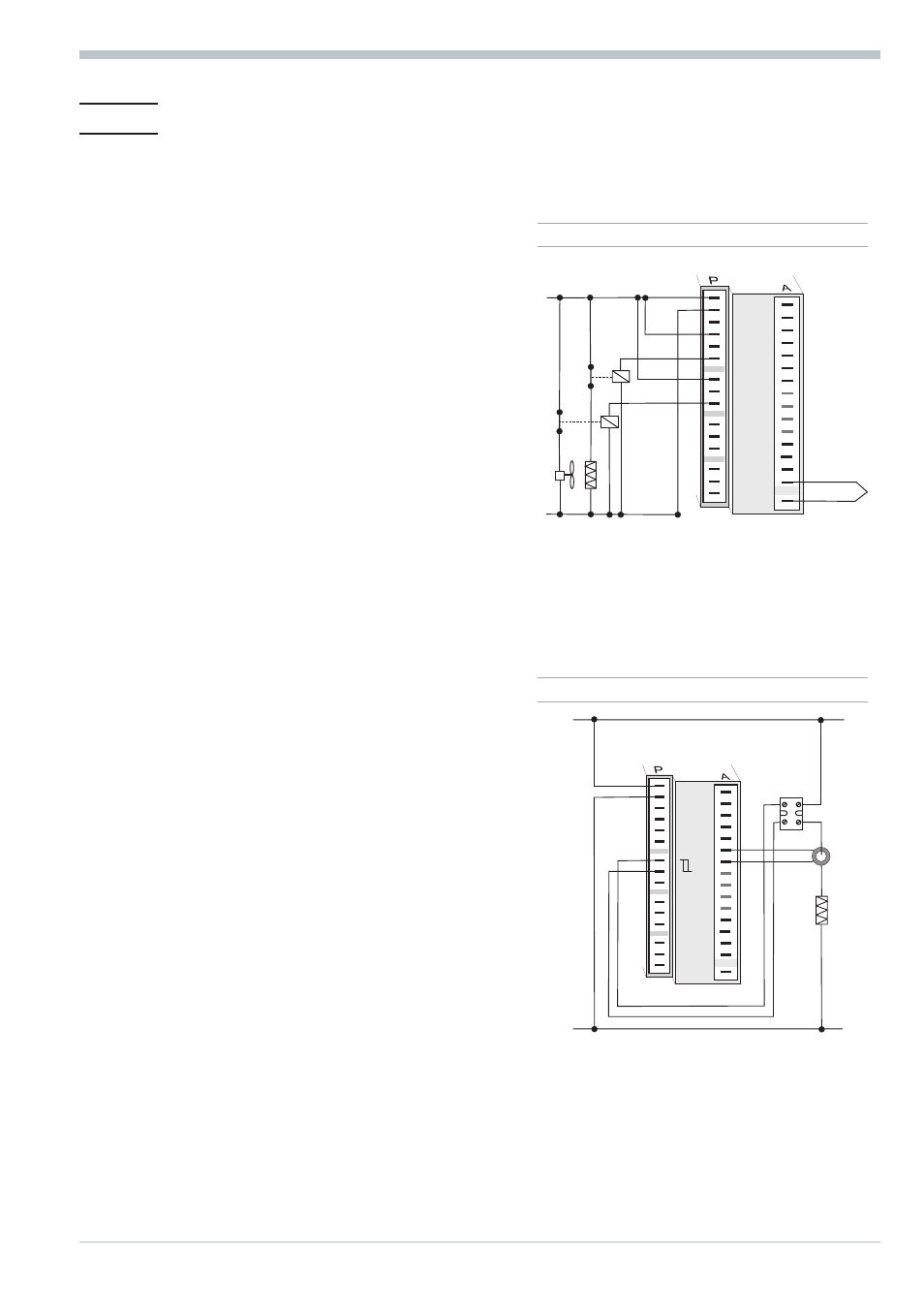
Connection of outputs OUT1/2
2
Relay outputs (250V/2A), potential-free
changeover contact
Connection of outputs OUT3/4 3
a relay (250V/2A), potential-free
changeover contact universal output
b current (0/4...20mA)
c voltage (0/2...10V)
d transmitter supply
e logic (0..20mA / 0..12V)
Connection of input INP1 4
Input mostly used for variable x1
(process value)
a thermocouple
b resistance thermometer (Pt100/ Pt1000/ KTY/ ...)
c current (0/4...20mA)
d voltage (0/2...10V)
Connection of input INP2 5
f heating current input (0..50mA AC)
or input for ext. set-point (0/4...20mA)
g potentiometer input for position
feedback
Connection of input INP2 5
a Heating current input (0...50mA AC)
or input for ext. Set-point (0/4...20mA)
b Potentiometer input for position
feedback
Connection of input INP3 6
As input INP1, but without voltage
Connection of inputs di1, di2 7
Digital input, configurable as switch or
push-button
Electrical connections
8800 process controller
7
Terminal connection
6
9
10
11
12
13
14
15
1
2
3
4
5
6
7
8
9
10
11
12
13
14
17
(16)
L
N
+
5
4
3
2
1
8
7
15
2 OUT1/2 heating/cooling
L
N
+
_
SSR
3
4
5
6
9
10
11
12
13
14
15
1
2
3
4
5
8
9
10
11
12
13
14
15
17
(16)
2
1
8
7
6
7
Logik
5 INP2 current tansformer