Usb interfaces (j15a/b, j21a/b), Primary usb0 and usb1 (j15a/b), Secondary usb2 and usb3 (j21a/b) – Ampro Corporation Single Board Computer 700 User Manual
Page 49
Chapter 3
Hardware
ReadyBoard 700
Reference Manual
43
USB Interfaces (J15A/B, J21A/B)
The ReadyBoard 700 contains one root USB hub with four functional USB ports. The PC-style (or
Standard) connector (J5A/B) provides two of the four USB ports (USB0 and USB1). The other two
USB ports share a single 10 pin header (J21A/B) on the board.
Features implemented in the USB ports include the following:
•
One root hub and two USB ports on connector (J15A/B)
•
One root hub and two USB ports on connector (J21A/B)
•
USB v.1.1 and Universal OHCI v.1.1 compatible
•
Integrated physical layer transceivers
•
Over-current fuses, located on the board, are used on all four USB ports
•
USB0 and USB1 have independent fuses and USB2 and USB3 share a single fuse on the board.
See Table 2-4.
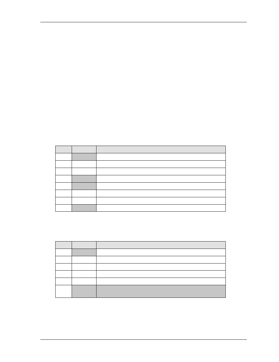
Primary USB0 and USB1 (J15A/B)
Table 3-15. USB 1 & 2 Interface Pin/Signal Descriptions (J15/B)
Pin #
Signal
Description
1
+5V
+5V through a fuse (F1)
2
USBP0-
Universal Serial Bus Port 0 Data Negative
3
USBP0+
Universal Serial Bus Port 0 Data Positive
4
GND
Goes to ground thorough a choke
5
+5V
+5V ±5% through a fuse (F3)
6
USBP1-
Universal Serial Bus Port 1 Data Negative
7
USBP1+
Universal Serial Bus Port 1 Data Positive
8
GND
Goes to ground thorough a choke
Notes: The shaded area denotes power or ground.
Secondary USB2 and USB3 (J21A/B)
Table 3-16. USB 2 & 3 Interface Pin/Signal Descriptions (J21A/B)
Pin #
Signal
Description
1, 2
+5V
+5V ±5% through a fuse (F4)
3
USBP2-
Universal Serial Bus Port 2 Data Negative
4
USBP3-
Universal Serial Bus Port 3 Data Negative
5
USBP2+
Universal Serial Bus Port 2 Data Positive
6
USBP3+
Universal Serial Bus Port 3 Data Positive
7, 8,
9, 10
GND
Goes to ground thorough a choke
Notes: The shaded area denotes power or ground.