Serial interfaces (j5a/b, j3a/b), Figure 3-1. rs485 serial port implementation – Ampro Corporation Single Board Computer 700 User Manual
Page 45
Chapter 3
Hardware
ReadyBoard 700
Reference Manual
39
Serial Interfaces (J5A/B, J3A/B)
The ReadyBoard supports 4 independent serial ports, using two separate chips. The Southbridge
(VT86C686B) provides serial ports 1 and 2 through the Serial A DB9 connector (J5A/B) and the
Secondary I/O chip (W83877TF) provides serial ports 3 and 4 through Serial B connector (J3A/B).
The four serial ports support the following features:
•
Four individual 16550-compatible UARTs
•
Programmable word length, stop bits and parity
•
16-bit programmable baud rate generator
•
Interrupt generator
•
Loop-back mode
•
Four individual 16-bit FIFOs
•
Wake on Ring feature
•
Serial A supports ports 1 and 2 using the Southbridge/Super I/O
♦
Serial Port 1 (COM1) supports RS232 and full modem support
♦
Serial Port 2 (COM2) supports RS232, and full modem support
•
Serial B supports ports 3 and 4 using the Secondary I/O Controller
♦
Serial Port 3 (COM3) supports RS232/RS485/RS422 and full modem support
♦
Serial Port 4 (COM4) supports RS232/RS485/RS422 and modem support
NOTE
The RS232/RS485/RS422 modes are selected in BIOS Setup under BIOS
and Hardware Settings screen for Serial ports 3 (COM3) and 4 (COM4).
However, the RS232 mode is the default (Standard) for any serial port.
RS485 mode termination is selected with jumper JP6, pins 1-2 (COM3),
and pins 3-4 (COM4), when the RS485 mode is selected in BIOS Setup.
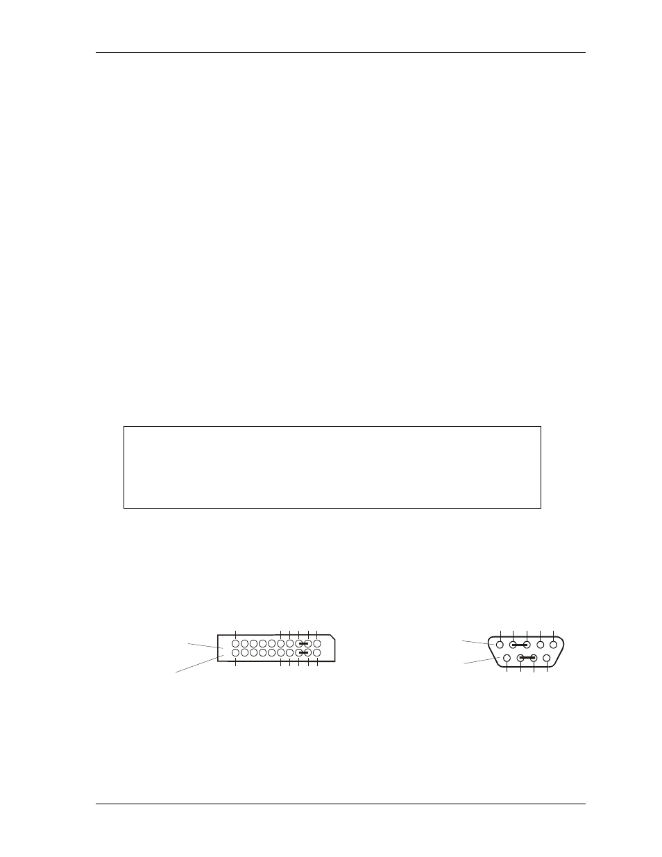
To implement the two-wire RS485 mode on either serial port, you must tie the equivalent pins together
for each port.
For example; on Serial Port 3, tie pin-3 (RX3-) to -5 (TX3-) and pin-4 (TX3+) to -6 (RX3+) at the Serial
B interface connector (J3) as shown in Figure 3-1. As an alternate, tie pin-2 to -3 and pin-7 to -8 at the
DB9 serial connector for Serial Port 3 as shown in Figure 3-1. Refer also to the following tables for the
specific pins for the other ports and connectors. The RS422 mode uses a four-wire interface and does
not need any pins tied together, but you must select RS485 in BIOS Setup.
Serial B Interface (J3)
for Serial Port 3
(or COM3 Port)
1
2
3
4
5
6
7
8
9
10
20
19
Top View
5
4
3
2
1
9
8
7
6
Standard DB9 Serial
Port Connector (Female)
Rear View
Or
R
B
700R
S
4
8
5
Co
n
B
Figure 3-1. RS485 Serial Port Implementation
Tables 3-12 and 3-13 list the pins and corresponding signals for the Serial A interface connector (J5A/B,
Serial Ports 1 and 2) and Table 3-14 list the pins and corresponding signals for the Serial B interface
connector (J3A/B, Serial Ports 3 and 4).