Ampro Corporation Single Board Computer 700 User Manual
Page 44
Chapter 3
Hardware
38
Reference Manual
ReadyBoard 700
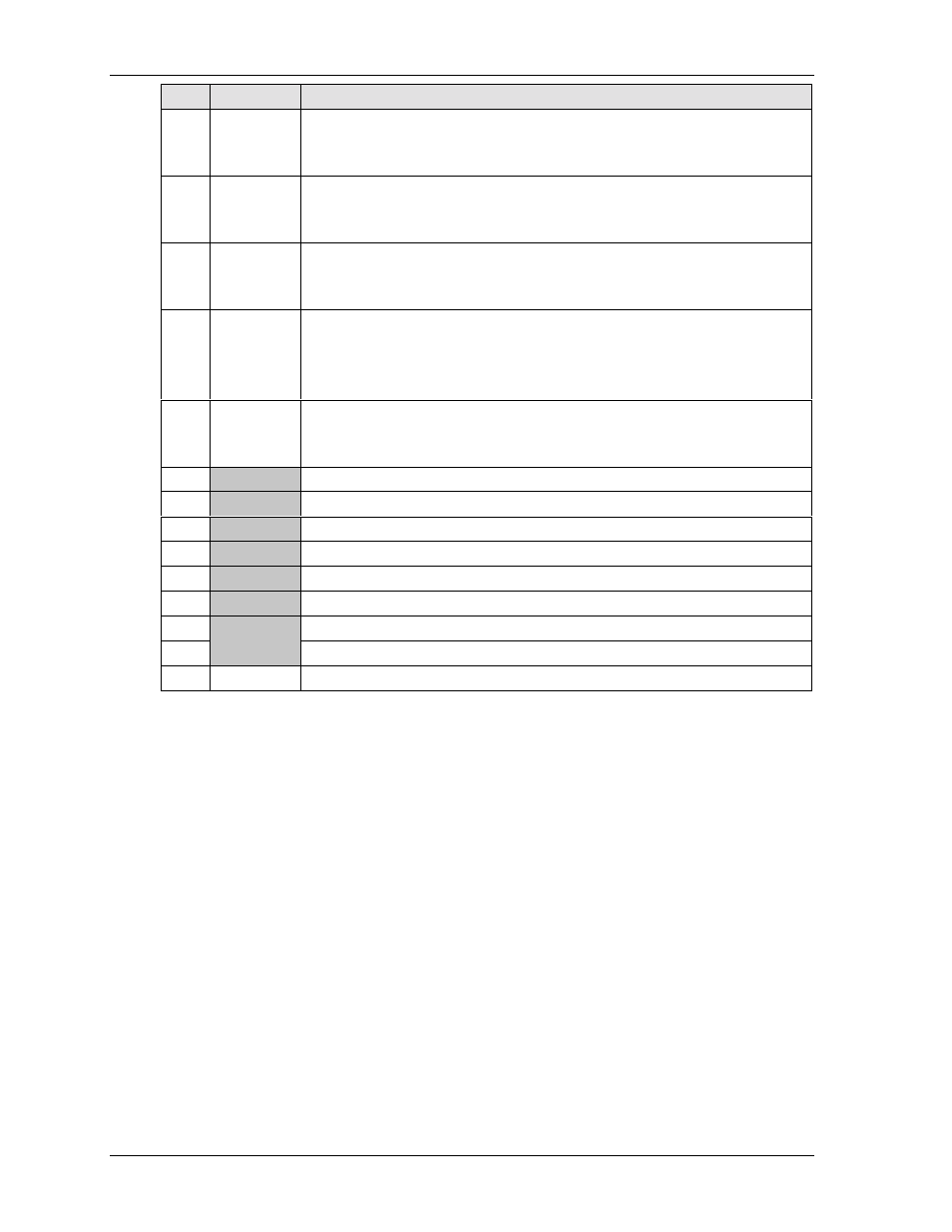
Pin #
Signal
Description
13
SLCTIN
STEP*
Select In – This output signal to the printer is used to select the printer. I/O pin
in ECP/EPP mode.
Step – Low pulse for each track-to-track movement of the head.
14
AUTOFDX*
DRVENO
Auto Feed* – This is a request signal into the printer to automatically feed one
line after each line is printed.
Floppy Drive Density Select 0 –
15
ERR*
HDSEL*
Error – This is a status output signal from the printer. A Low State indicates an
error condition on the printer.
Head Select – Selects side for Read/Write operations (0 = side 1, 1 = side 0)
16
PINIT*
DIR*
Printer Initialize* – This signal used to Initialize printer. Output in standard
mode, I/O in ECP/EPP mode.
Direction – Head movement direction (0 = inward motion,
1 = outward motion).
17
PTSLCT
WGATE*
Printer Select – This is a status output signal from the printer. A High State
indicates it is selected and powered on.
Write Gate – Signal to the drive to enable current flow in the write head.
18
GND
Digital Ground
19
GND
Digital Ground
20
GND
Digital Ground
21
GND
Digital Ground
22
GND
Digital Ground
23
GND
Digital Ground
24
GND
Digital Ground
25
GND
Digital Ground
26
NC
Not Connected
Notes: The shaded area denotes power or ground. The signals marked with * = Negative true logic.