Jumper definitions, Led definitions, Power/ide led definitions – Ampro Corporation Single Board Computer 700 User Manual
Page 20
Chapter 2
Product Overview
14
Reference Manual
ReadyBoard 700
Jumper Definitions
Table 2-5 describes the jumpers shown in Figure 2-6. Refer to the Oops! Jumper to clear the BIOS.
Table 2-5. Jumper Settings
Jumper #
Installed
Removed
JP1 – TFT/LCD Clock
Clock Invert (pins 1-2)
Clock Normal (pins 2-3) Default
JP2 – LCD Voltage Type
Enable +3.3V (pins 1-2) Default
Enable +5V (2-3)
JP3 – CMOS Normal/Clear
Normal (pins 1-2) Default
Clears Time & Date only (pins 2-3)
JP4 – CF Master/Slave
Master (pins 1-2) Default
Slave (removed)
JP5 – Flash BIOS
Internal (pins 1-2) Default
External (removed)
JP6 – COM3 RS485
Termination (pins 1-2)
No Termination (removed) Default
JP6 – COM4 RS485
Termination (pins 3-4)
No Termination (removed) Default
LED Definitions
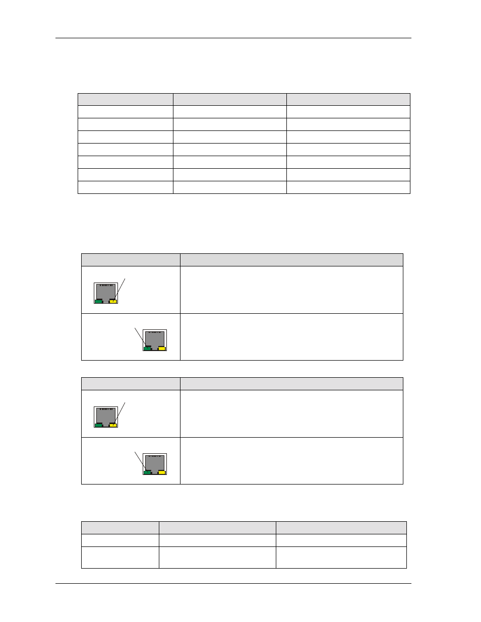
Tables 2-6 and 2-7 provide the LED colors and definitions for the Ethernet ports, Port 1 (J10) and Port 2
(J11) located on the ReadyBoard 700. Refer to Figures 2-4 and 2-8.
Table 2-6. Ethernet Port 1 (J10) LED Indicators
Indicator
Definition
Ethernet
Link/Activity
LED
Link/Activity LED – This yellow LED is the activity/link indicator
and provides the status of Ethernet port 1 (J10).
•
A steady On LED indicates a link is established
•
A flashing LED indicates active data transfers
Ethernet
Speed LED
Speed LED – This green LED is the Speed indictor and indicates
transmit or receive speed of Ethernet port 1 (J10).
•
A steady Off LED indicates the port is at 10BaseT speed
•
A steady On LED indicates the port is at 100BaseT speed
Table 2-7. Ethernet Port 2 (J11) LED Indicators
Indicator
Definition
Ethernet
Link/Activity
LED
Link/Activity LED – This yellow LED is the activity/link indicator
and provides the status of Ethernet port 2 (J11).
•
A steady On LED indicates a link is established
•
A flashing LED indicates active data transfers
Ethernet
Speed LED
Speed LED – This green LED is the Speed indictor and indicates
transmit or receive speed of Ethernet port 2 (J11).
•
A steady Off LED indicates the port is at 10BaseT speed
•
A steady On LED indicates the port is at 100BaseT speed
Power/IDE LED Definitions
Table 2-8. Power/IDE Activity LED Indicators (D4)
LED#
Activity
No Activity
LED stack (D4)
Steady Green = Power On
Steady Off = Power Off
LED stack (D4)
Flashing Yellow = IDE activity
(IDE drive or CompactFlash)
Steady Off = No IDE activity