Ampro Corporation Single Board Computer 700 User Manual
Page 40
Chapter 3
Hardware
34
Reference Manual
ReadyBoard 700
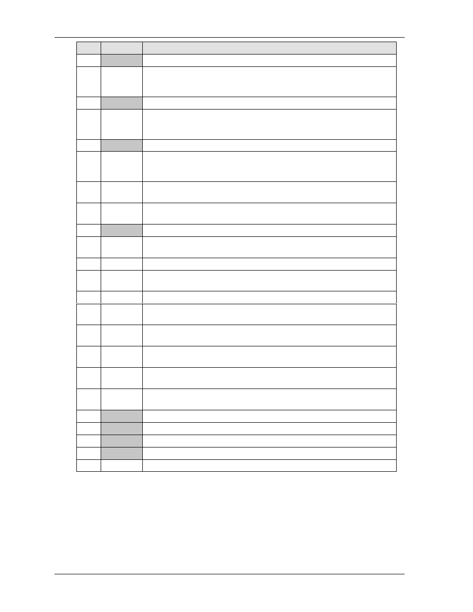
Pin #
Signal
Description
22
GND
Digital Ground
23
PDIOW*
Primary Device I/O Read/Write Strobe – Strobe signal for write functions.
Negative edge enables data from a register or data port of the drive onto the
host data bus. Positive edge latches data at the host.
24
GND
Digital Ground
25
PDIOR*
Primary I/O Read/Write Strobe – Strobe signal for read functions. Negative
edge enables data from a register or data port of the drive onto the host data
bus. Positive edge latches data at the host.
26
GND
Digital Ground
27
PDIORDY
Primary I/O Channel Ready – When negated extends the host transfer cycle of
any host register access when the drive is not ready to respond to a data
transfer request. High impedance if asserted.
28
PDCSEL
Primary Cable Select – Used to configure IDE drives as device 0 or device 1
using a special cable.
29
PDDACK* Primary DMA Channel Acknowledge – Used by the host to acknowledge data
has been accepted or data is available. Used in response to DMARQ asserted.
30
GND
Digital Ground
31
IRQ14
Interrupt Request 14 – Asserted by drive when it has pending interrupt (PIO
transfer of data to or from the drive to the host).
32
NC
Not connected (IOCS16*)
33
PDA1
Primary IDE ATA Disk Address (0 to 2). Used to indicate which byte in the
ATA command block or control block is being accessed
34
PD33/66
UDMA 33/66 Sense – Senses which DMA mode to use for IDE devices.
35
PDA0
Primary IDE ATA Disk Address (0 to 2). Used to indicate which byte in the
ATA command block or control block is being accessed
36
PDA2
Primary IDE ATA Disk Address (0 to 2). Used to indicate which byte in the
ATA command block or control block is being accessed
37
PDCS1*
Primary Slave/Master Chip Select 1 – Used to select the host-accessible
Command Block Register.
38
PDCS3*
Primary Slave/Master Chip Select 3 – Used to select the host-accessible
Command Block Register.
39
IDE LED1
IDE Activity –Indicates IDE drive activity to yellow IDE LED (D4) on card
edge..
40
GND
Digital Ground
41
+5V
+5 volt power ±10%
42
+5V
+5 volt power ±10%
43
GND
Digital Ground
44
NC
Not connected
Notes: The shaded area denotes power or ground. The signals marked with * = Negative true logic.