Ampro Corporation Single Board Computer 700 User Manual
Page 24
Chapter 2
Product Overview
18
Reference Manual
ReadyBoard 700
R
B
7
00sid
e
vie
w
01
1.
1
1
3
6.500
0.200
Mounting
Hole Center at (4) Corners (x 8 dims)
0.345
1.214
1.213
0.640
0.
1
2
0
0.
3
6
1
0.311
0.500
0.051
0.
4
9
7
0.547
0.067
0.100
0.055
0.602
0.650
0.554
0.510
0.072
0.275
0.
2
7
5
0.180
0.
3
9
0
0
.080
0.370
1.875
1.350
0.338
0.624
0.624
0.068
0.696
All Dimensions in this drawing section are in Inches within +/- 0.009”
Board thickness is 0.062”
28
.2
7
0
165.1
5.080
Mounting
Hole Center at (4) Corners (x 8 dims)
8.763
30.835
30.810
16.256
3.
0
4
8
9.
1
6
9
7.899
12.700
1.295
1
2
.623
13.893
1.701
2.54
1.391
15.290
16.510
14.071
12.954
1.828
6.985
6.
98
5
4.572
9.9
0
6
2
.032
9.398
47.625
34.29
8.588
15.849
15.849
1.727
17.678
All Dimensions in this drawing section are in Millimeters within +/- 0.25mm
Board thickness is 1.574mm
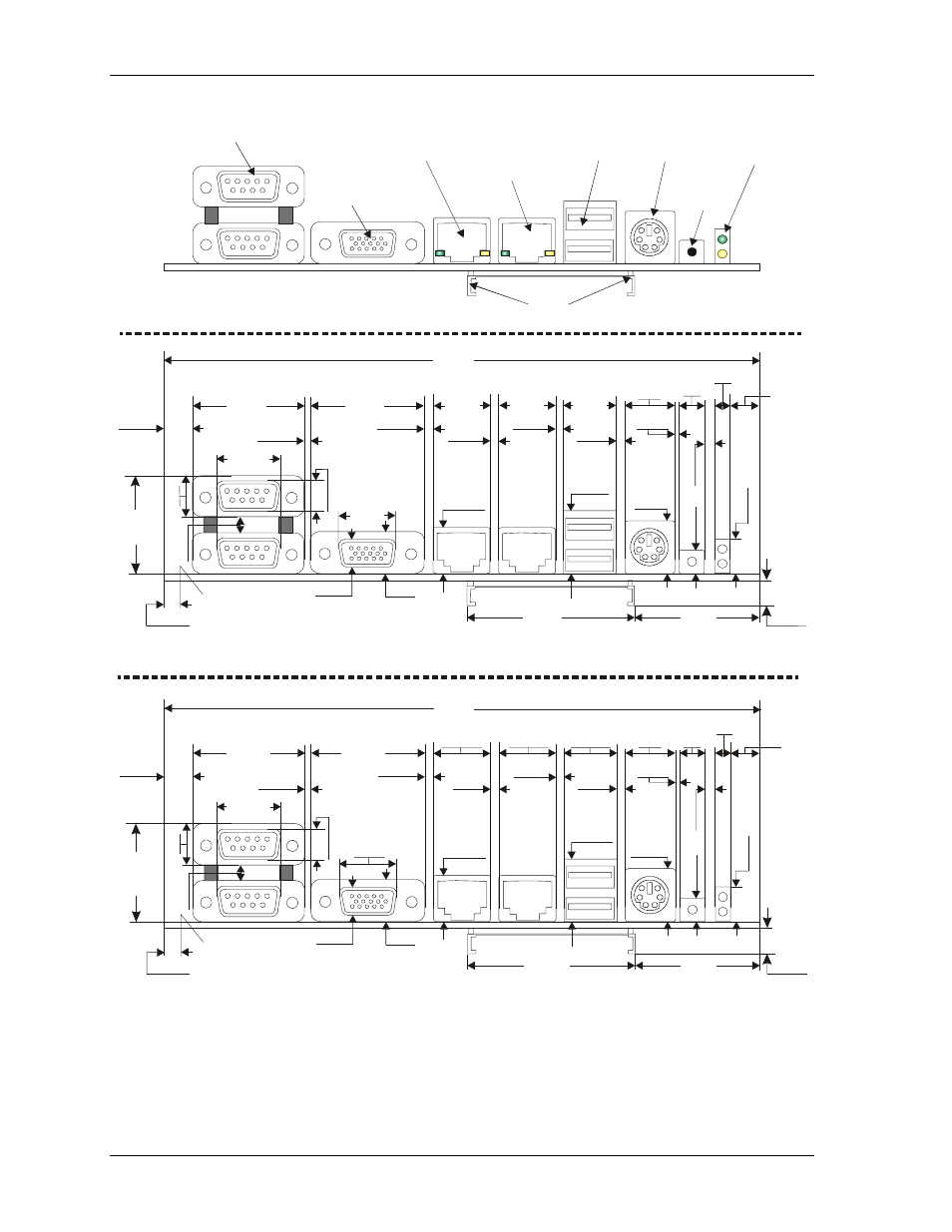
Serial 1 & 2 (J5A/B)
(Serial 1 Lower)
CRT (J8)
Ethernet 1
(J10)
Ethernet 2
(J11)
USB 0 & 1
(J15A/B)
(USB 0 Lower)
Keyboard/
Mouse
(J16A/B)
Reset
Switch
(SW1)
Power/IDE
Activity
LED (D4)
CompactFlash Socket (J23)
ReadyBoard 700 (Side view)
Figure 2-8. ReadyBoard 700 Panel Dimensions (Side view)