Ampro Corporation Single Board Computer 700 User Manual
Page 21
Chapter 2
Product Overview
ReadyBoard 700
Reference Manual
15
R
B
700_01cb
U6
U4
Y1
D1
J6
J4
J3
J2
J26
J1
U3
J5
J8
J7
J9
J10
J11
J15
J16
SW1
J19
J18
U14
U15
X2
X1
U11
U9
U10
U7
U8
Y2
Y3
JP2
J12
J1
7
D2
U13
U12
J22
J20
J21
U1
U2
JP3
JP4
JP5
BT
1
D4
JP6
JP1
U33
4
3
2
U12
U5
Q11
U32
J14
J13
1
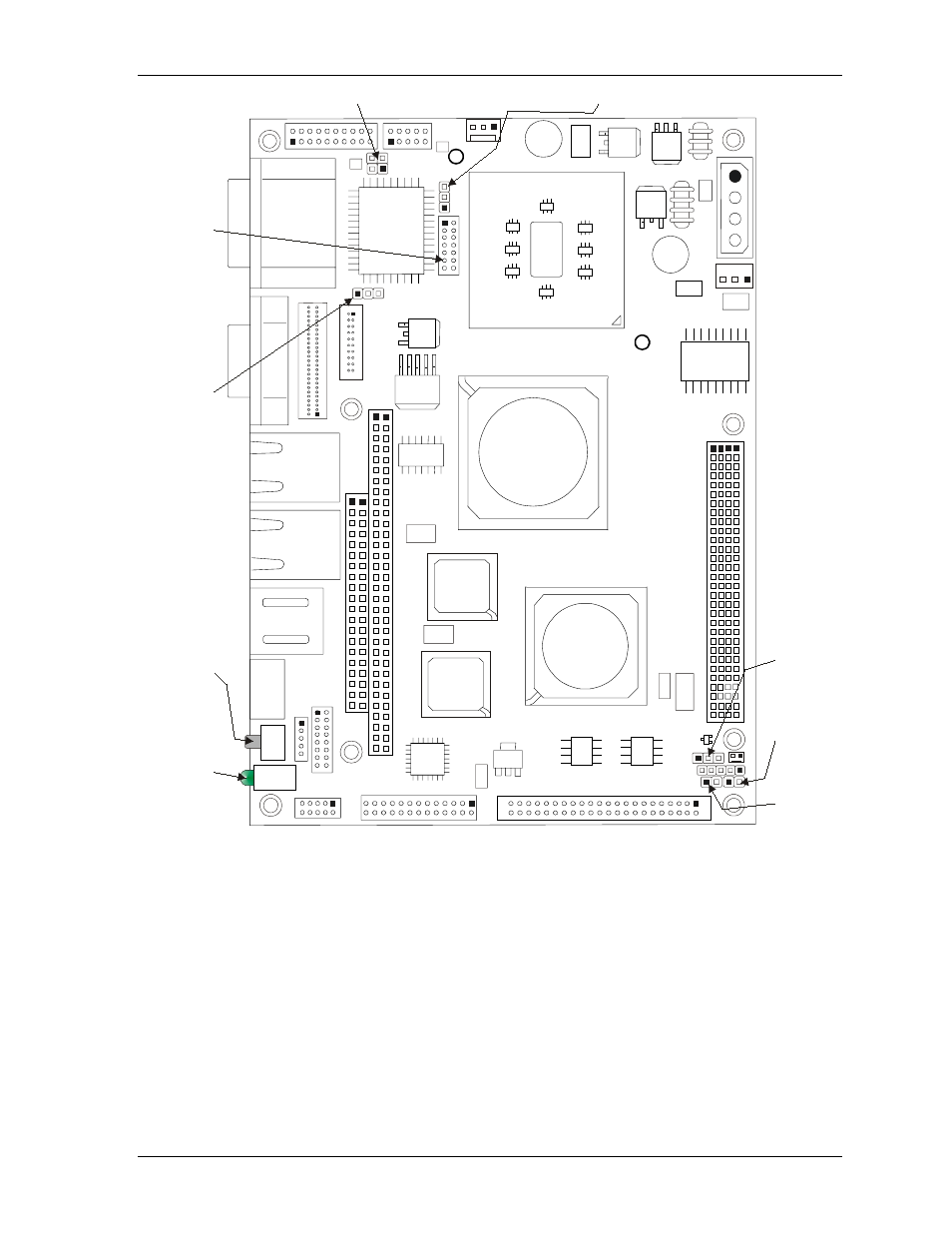
Reset
Switch
(SW1)
Power
On/
IDE
Activity
LEDs
(D4)
TFT/LCD Clock (JP1)
Reserved
Factory
use only
(J26)
Flash
BIOS
(JP5)
CMOS
Normal/
Clear
(JP3)
CF
Master/
Slave
(JP4)
Serial B (COM3/COM4) RS485 Termination (JP6)
LCD
Voltage
Setting
(JP2)
Figure 2-6. Jumper, Switch, and LED Locations (Top view)