GW Instek PSP Series User Manual
Page 12
PSP SERIES
USER MANUAL
18
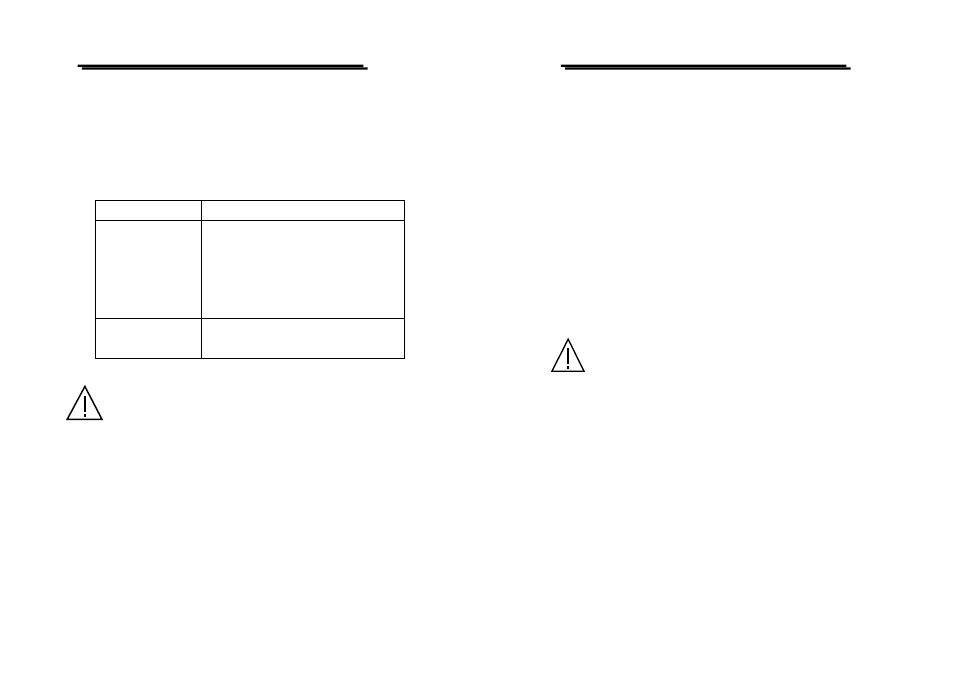
8. Rectification of faults
With the PSP series power supply you have acquired a new generation
measuring instrument constructed to the latest technological standards.
However, faults can occur. Because of this, the following describes
how some of these problems can be resolved by the user relatively
easily:
Problem
Possible solution
No display
Is the instrument switched on?
Is the AC power plug making good contact
both in the instrument and in the AC power
socket?
Is the AC fuse OK?
No input possible
"REM" or "LOCK" key pressed; see under
section C or F
Attention: Except when this is possible manually, the opening
of covers or removal of parts can expose voltage-carrying
components. Connection points may also be live. Before any
adjustment, maintenance, repair or exchange of parts or
assemblies requiring opening of the unit, the unit must be
disconnected from all voltage sources and measurement
circuits. If the adjustment maintenance or repair is
subsequently required for the open unit, these must only be
performed by a specialist familiar with the associated
hazards and relevant regulations (VDE-0100, VDE-0701,
VDE0683).
Capacitors within t he instrument can remain charged
even when the unit has been disconnected from all voltage
sources and measurement circuits.
PSP SERIES
USER MANUAL
19
9. Maintenance
The following instructions are executed by qualified personnel only. To avoid
electrical shock, do not perform any servicing other than the operating instructions
unless you are qualified to do so.
9-1.Fuse Replacement
If the fuse blown, the CV or CC indicators will not light and the
power supply will not operate. The fuse should not normally blow
unless a problem has developed in the unit. Try to determine and
correct cause of the blown fuse, then replace only with a fuse of the
correct rating and type. The fuse is located on the rear panel (see Fig.
4-2).
WARNING: For continued fire protection. Replace with
250V fuse of the specified type and rating, and disconnect
the power cord before replacing fuse.
9-2.Line Voltage conversion
The primary winding of the power transformer is tapped to permit
operation from 115/230 VAC, 50/60 Hz line voltage. Conversion from
one line voltage to another is done by change AC selects switch as
shown in Fig. 4-2.
To convert to different line voltage, perform the following procedure:
(1) Make sure the power cord is unplugged.
(2) Set the AC switch to the desired line voltage position.