1 dact-ud2 installation – Fire-Lite DACT-UD2 Digital Alarm Communicator/Transmitter User Manual
Page 14
DACT-UD2 Installation
14
DACT-UD2 Communicator PN 53037:B 4/01/08
2.1.1 DACT-UD2 Installation
WARNING! Disconnect all sources of power (AC and DC) before installing or
removing any modules or wiring.
The DACT-UD2 module plugs into connector J2 on the FACP main circuit board.
The following steps must be followed when installing the DACT-UD2 module:
1. Remove all power (AC and DC) from FACP before proceeding with installation
2. Remove all main circuit board mounting screws (6 locations) and the 4XTMF
module standoffs (2 locations), unplug the power supply cable from J1 and lift
the main circuit board assembly off the chassis (refer to Figure 2.1)
3. Remove the Keypad/Display from the main circuit board as described in the
beginning of this section
4. Remove and discard the Keypad/Display support standoff that presently occupies
DACT-UD2 standoff location #3 (refer to Figure 2.3)
5. Install the supplied DACT-UD2 female/female standoffs in the three locations
shown in Figure 2.3 and secure with the three supplied screws, inserted from the
bottom side of the main circuit board. Be sure to tighten them fully.
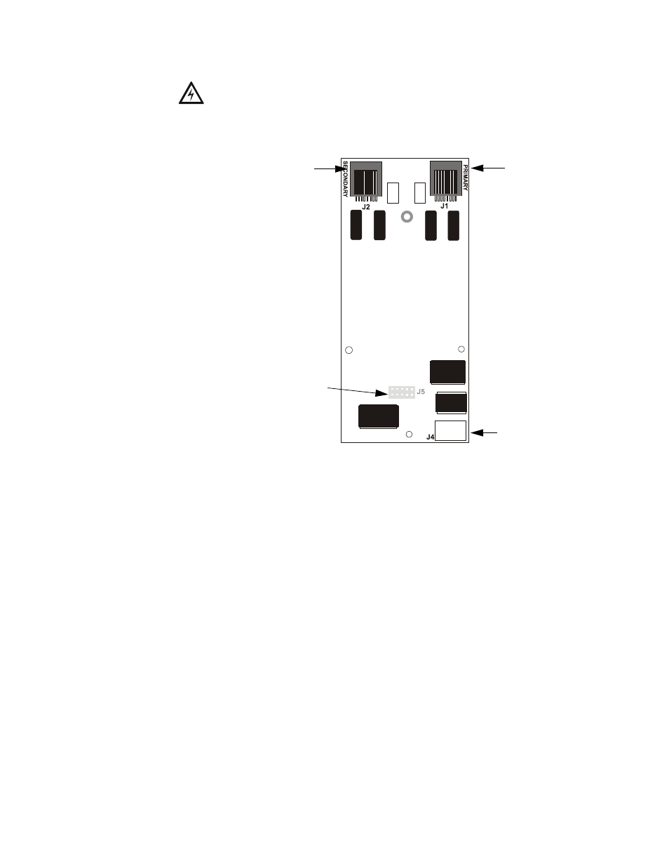
6. Carefully plug connector J5 on back of the DACT-UD2 module into connector J2
on the FACP main circuit board, being careful not to bend any pins
Figure 2.2 DACT-UD2 Module
SEC
Secondary Phone Line
J5 Connector (located on back
of module) plugs into J2 on
FACP main circuit board
PRI
Primary Phone Line
DIALX
.CDR
J4
USB Connector