Section 2 dact-ud2 installation, 1 installation in ms-9600ls facp, Dact-ud2 installation – Fire-Lite DACT-UD2 Digital Alarm Communicator/Transmitter User Manual
Page 13: Figure 2.1 keypad/display removal
DACT-UD2 Installation
DACT-UD2 Communicator PN 53037:B 4/01/08
13
SECTION 2
DACT-UD2 Installation
2.1 Installation in MS-9600LS FACP
WARNING! Disconnect all sources of power (AC and DC) before installing or
removing any modules or wiring.
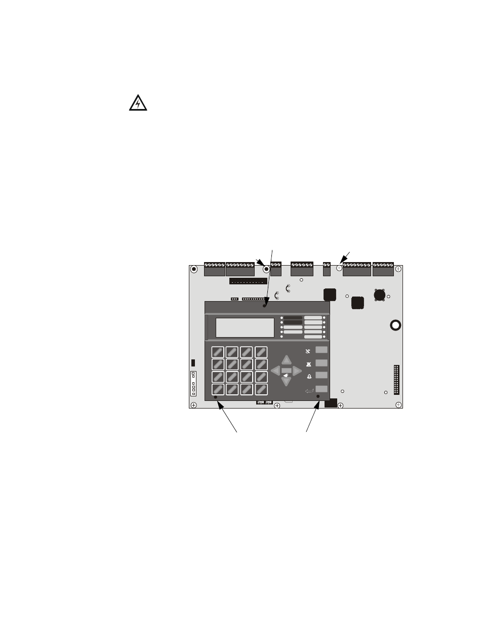
FACP Keypad/Display Removal
Removal of the keypad/display is normally not necessary. If, however, it becomes
necessary to replace the keypad/display, access the auxiliary trouble bus connectors at
J16 and J17 or install the DACT-UD2 option module on J2, the Keypad/Display can be
removed by inserting a Phillips screwdriver into each of the three holes located in the
flexible covering of the Keypad/Display and loosening the three mounting screws.
Note that it is not necessary to disconnect the cables between the Keypad/Display and
the main circuit board unless the unit itself is being replaced. Carefully lift the Keypad/
Display and rest the unit at the bottom of the main circuit board.
Note: When installing the DACT-UD2, the main motherboard must be removed from
the chassis. Unplug the power supply cable from J1 before proceeding.
+BATTERY-
LCD DISPLAY
KEYPAD I/F
1
2
3
OPT DACT
J3
J2
TB1
TB2
TB3
JP3
JP2
JP8
JP4
JP7
JP5
JP6
JP6
J17
J16
J6
J8
J7
JP10
REMOVE
TO DISABLE
LOCAL
CHARGER
DISABLE
GND
FLT
CUT TO
MONITOR 4XTM
OPT SLC
4XTM OPT BD
TB4
TB5
TB6
TB7
TB8
1
4
*
2
5
0
3
6
#
1
st
EVENT
ABC
DEF
GHI
JKL
MNO
PRS
TUV
WXY
QZ
-/.
CLR
7
8
9
ESC
ENTER
RECALL
ACK/STEP
ALARM
SILENCE
DRILL
HOLD 2 SEC
RESET
MODE
MAINTENANCE
ALARM
SILENCED
DISABLED
BATTERY
GROUND
TROUBLE
SUPERVISORY
FIRE ALARM
AC POWER
TB1
J1
Figure 2.1 Keypad/Display Removal
Keypad/Display Mounting
Screw Access Hole
Keypad/Display Mounting
Screw Access Holes
96da
ct1.cdr
standoff
screw
screw
screw
standoff
screw
screw
screw