Fire-Lite CHG-120F Battery Charger User Manual
Page 23
Installing Optional Meters
Installing the Charger
CHG-120F Instruction 03/21/01 PN 50888:B0
23
Installing a VM-1 - A VM-1 can be connected across a charger output circuit. For
example, to install a VM-1 to measure voltage from charger output circuit 1, follow these
steps:
1.
Mount the VM-1 into a mounting slot on the front of the BB-55F battery box.
2.
Connect the positive lead to TB2 Out 1 (+). See Figure 15.
3.
Connect the negative lead to TB2 Out 1 (–). SeeFigure 15.
Installing an MPM-3 To install an MPM-3, follow these steps:
1.
Connect the AM-1 (Figure 15).
2.
Connect the VM-1 (Figure 15).
3.
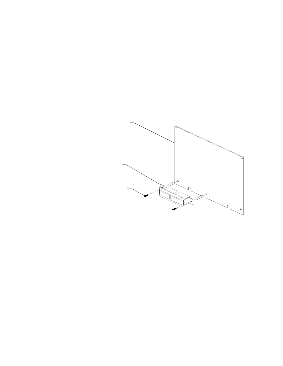
Mount the MPM-3 onto a power supply connected to your system, such as an
MPS-24F or MPS-24AF (Figure 17).
Figure 17 Mounting an MPM-3
Power supply board
(MPS-24F or
MPS-24AF)
MPM-3
Mounting screws
- 2401B Circuit Board Standoff Placement (1 page)
- 411UDAC Fire Alarm Communicator (84 pages)
- 411UDAC Dig C Digital Communica unicatortor (1 page)
- 411UDAC Communicator Dress Panel (2 pages)
- 411UDAC Communicator Circuit Board & Transformer (2 pages)
- 411UDAC Fire Alarm Communicator Relay (1 page)
- ACC-25/50 Audio Command Center (1 page)
- ACC-25/50DA Distributed Audio Panel (84 pages)
- ACC-25/50ZS (1 page)
- ACM-16ATF Annunciator Modules (68 pages)
- ACM-8RF Control Relay Module (48 pages)
- APS-6RF Auxiliary Power Supply (28 pages)
- B524BI Plug-in Isolator (4 pages)
- B524RB(A) Plug-in Relay Detector Bases (4 pages)
- B310LP Plug-in Base for Addressable Detector (2 pages)
- B350LP Plug-In Base for Addressable Detector (4 pages)
- BB-55 Battery Box (1 page)
- BG-12 Series Manual Pull Stations (4 pages)
- BG-12LA Manual Pull Station (2 pages)
- BG-12LAO Manual Pull Station (2 pages)
- BG-12LO Manual Pull Station (2 pages)
- BG-12LPS Pre-Signal Manual Pull Station (2 pages)
- BG-12LR Agent Release Pull Station (2 pages)
- BG-12LX Addressable Pull Station (2 pages)
- BG-12SL Single Action Pull Station (2 pages)
- Central Station Receiver (1 page)
- CHG-120 Series Addendum - For Connection Of 100 Amp Hour Batteries (2 pages)
- CHG-75 Battery Charger (32 pages)
- CHS-6 Chassis (1 page)
- CHS-6 Chassis for BB-6 Cabinet (1 page)
- CMP-2401B Fire Alarm Control Panel (36 pages)
- CP355 Plug-in Addressable Ionization Sensor (2 pages)
- CRF-300 Relay Control Module (2 pages)
- DACT-UD2 Digital Alarm Communicator/Transmitter (52 pages)
- DP-4XF Dress Panel Kit PID (2 pages)
- ECC-50/100 Emergency Command Center (108 pages)
- ECC-50WBU Backup Amplifier (1 page)
- ECC-50DA/E Distributed Audio Amplifiers (26 pages)
- ECC-FFT (1 page)
- FCPS Series Field Charger/Power Supply (48 pages)
- FCPS Series Field Software Change Procedure (2 pages)
- FHSC-RF FIREFIGHTERS HANDSET STORAGE BOX (1 page)
- ECC-FFT Firefighters Telephone (32 pages)
- H350 Addressable Thermal Sensor (2 pages)