Installing optional meters – Fire-Lite CHG-120F Battery Charger User Manual
Page 22
Installing the Charger
Installing Optional Meters
22
CHG-120F Instruction 03/21/01 PN 50888:B0
Installing Optional Meters
You can also order and install a ammeter (AM-1), voltmeter (VM-1), or both (MPM-3) for
use with the charger. If mounting an AM-1 or a VM-1, mount the meter to a BB-55F as
shown in Figure 16. If mounting an MPM-3, mount to a power supply (Figure 17) installed
in a CAB-A3F or CAB-B3F. Table 6 contains descriptions and part numbers for these
optional meters:
Installing an AM-1 To install an AM-1, follow these steps:
1.
Cut jumper JP9 on the charger (Figure 15).
2.
Mount the AM-1 into a mounting slot on the front of the BB-55F (Figure 16).
3.
Connect the AM-1 harness to JP3 on the charger (Figure 15)—making sure to observe
proper polarity.
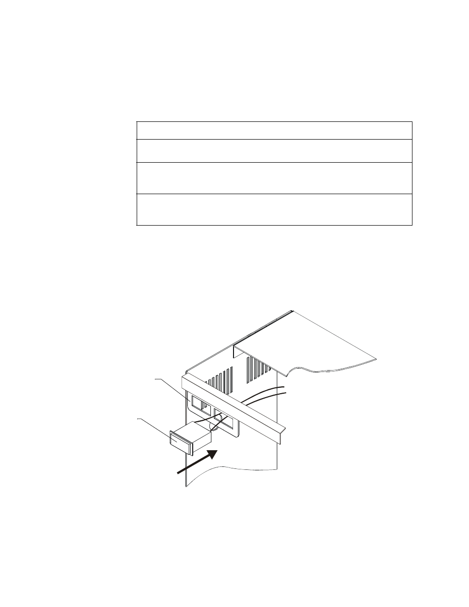
Figure 16 Mounting an AM-1 or VM-1 to a BB-55F Battery Box
Item
Part Number
Description
Ammeter
AM-1
0-10 A ammeter with a 3-ft. cable for connection to the
charger (JP3). Mounts into a BB-55F battery box only.
Voltmeter
VM-1
0-50 V voltmeter with 3-ft. positive and negative leads
for connection to the charger output circuit. Mounts
into a BB-55F battery box only.
Ammeter and
Voltmeter
Assembly
MPM-3
An AM-1 and VM-1 attached to a mounting bracket.
Mounts onto a power supply.
Table 6 Optional Meters
BB-55F Mounting Slot
AM-1 or VM-1
(BB-55F only)
M
ete
r-
BB
55.cd
r