Warning, Maintenance – Edwards Signaling HSL Series User Manual
Page 2
P/N 3100661 ISSUE 1
Maintenance
Light Source Replacement
1.
Loosen captive screws and remove cover of affected lens
module.
2.
Remove the light source assembly from the lens module.
3.
Install new light source assembly ensuring that the four prongs
on the PC board are aligned with the plug located in the back
of the lens module.
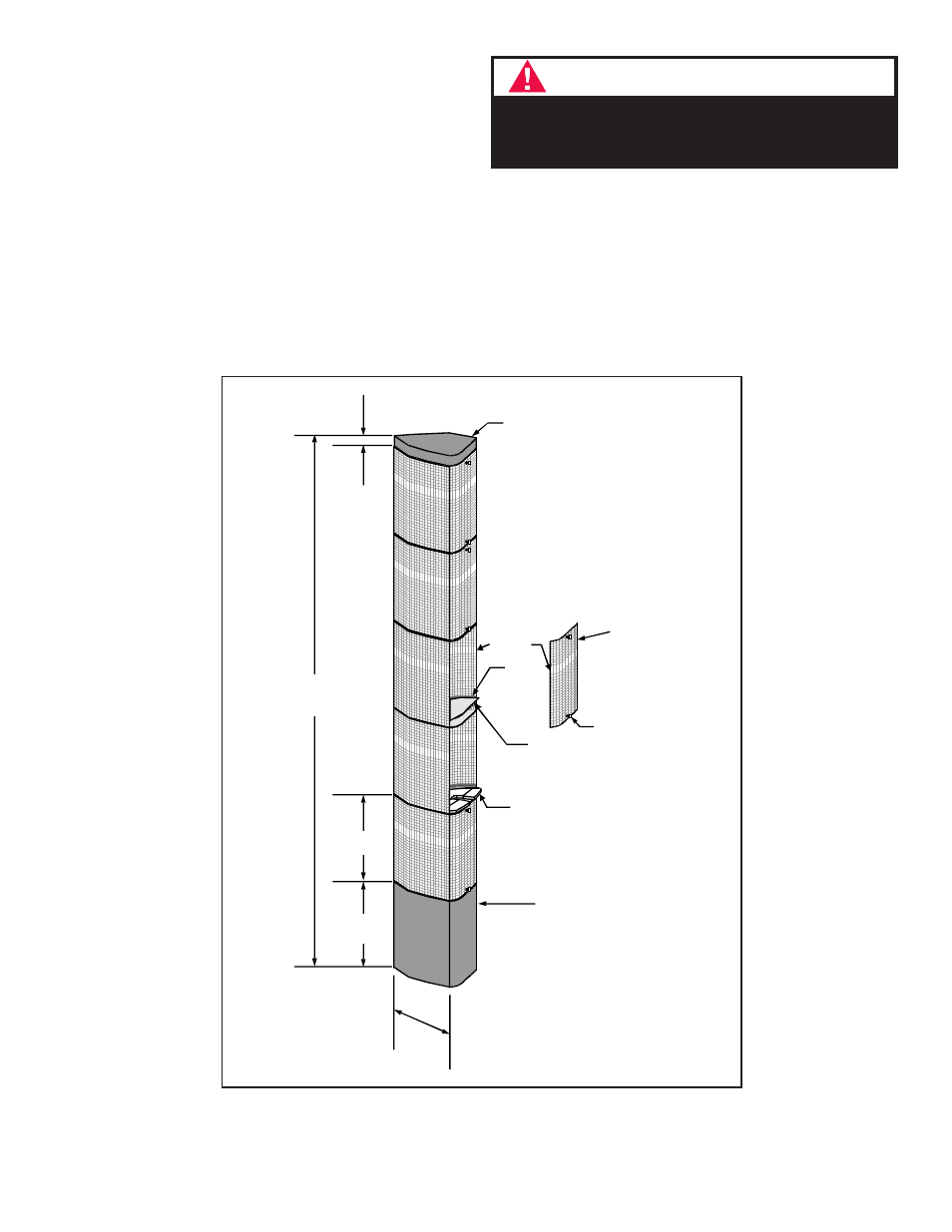
Figure 3. Assembling the Stackable Status Indicator (Cat. No. 102TBS shown for
illustration purposes only)
4.
Replace lens cover and secure using two captive screws.
Cleaning
The lens surfaces should be periodically dusted and cleaned with
a dry soft clean cloth to maintain optimum light visibility. If
necessary, the outside of the lens may be cleaned with water and a
mild detergent on a well rung-out, soft, clean cloth.
WARNING
To prevent leakage, ensure the magnifier ring on the
lens cover and the magnifier ring on the lens module
are aligned (Figure 3).
Cap (supplied with base)
Magnifier
Ring
Board
Groove
Lens Module
Cover
(2) Captive
Screws
Light Source
Assembly
Captive Key
Signal Base
(Cat. No. 102TBS shown)
3"
(76 mm)
3 5/8"
(92 mm)
3 5/8"
(92 mm)
22.25"
(565 mm)
1/2"
(13 mm)