Caution, Figure 5. wiring to terminal block tb1 – Edwards Signaling 5532MD User Manual
Page 3
P/N 3100358 ISSUE 1
PAGE 3
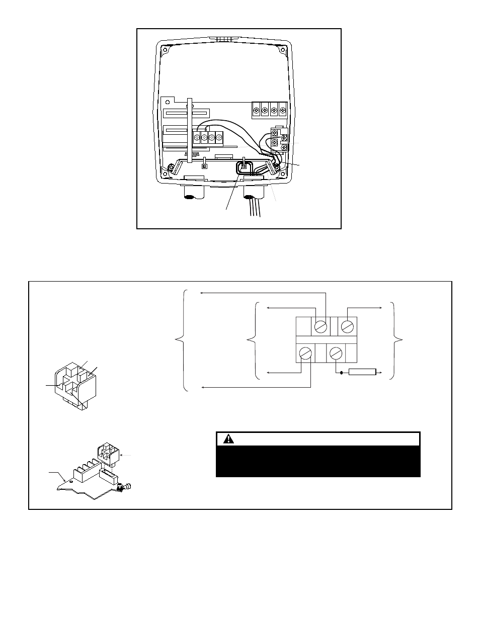
Figure 4. Wiring the 5532M Series Speaker/Amplifier
Plastic tie-wrap (provided)--
use to separate power leads
from signal and tone initiating leads
Signal leads to be connected
to Audio Coupler Board as
applicable.
Audio Coupler
Board
+24V DC Wiring
From Fire Panel
Figure 5. Wiring to Terminal Block TB1
2
1
4
3
2
4
1
3
Terminal Block
TB-1
Main
Board
(-)
(-)
(+)
(+)
(-)
(+)
To optional 24V DC
Battery Backup
From Control Panel
Signal Circuit
To Next Signal
or
End-of-Line Resistor
2
4
1
3
Polarity shown in alarm condition. Polarity reversed in
field wire monitoring condition of control panel.
CAUTION
To ensure proper supervision of connection, do not use
looped wires under terminal screws. Break wire run. Use
both sides of terminal screws as shown.
Diode Assembly
2600010
- 888D-N5 (4 pages)
- 888D-N5 (3 pages)
- 439D Series (3 pages)
- 101XBRM Series (5 pages)
- 104 GuardSwitch (2 pages)
- 105XBRi Series (5 pages)
- 250-CO (8 pages)
- 111 GuardSwitch (2 pages)
- 113 GuardSwitch (3 pages)
- 124 GuardSwitch (2 pages)
- 125 Class Halogen (4 pages)
- 125 Class Incand (2 pages)
- 125 Class Standard LED (2 pages)
- 125XBR LED (4 pages)
- 125XBRi Chameleon (4 pages)
- 126 GuardSwitch (2 pages)
- 128C GuardSwitch (2 pages)
- 215-F6 GuardSwitch (4 pages)
- 2302 SERIES (2 pages)
- 2315 Series (2 pages)
- 2400 Series (79 pages)
- 251-F6 (4 pages)
- 291-F6 (4 pages)
- 291-F7 (4 pages)
- 300 Series (4 pages)
- 300 Series (1 page)
- 301 (2 pages)
- 302 (2 pages)
- 5530M (8 pages)
- Genesis Signal Master Module (2 pages)
- ADTG4RB (2 pages)
- Genesis Speaker Strobe (4 pages)
- Genesis Remote Mount Signal Master Module (4 pages)
- EBPS Remote Booster Power Supply (64 pages)
- Genesis Temporal Horn (4 pages)
- Genesis Strobe (2 pages)
- Genesis Temporal Horn-Strobe (4 pages)
- Genesis Chime (2 pages)
- Genesis Chime-Strobe (4 pages)
- Genesis Ceiling Speaker (2 pages)
- Genesis Ceiling Strobe (2 pages)
- Genesis High Candela Ceiling Strobe (4 pages)
- Genesis Ceiling Speaker-Strobe (4 pages)
- Genesis High Candela Ceiling Speaker-Strobe (4 pages)
- Genesis Ceiling Horn-Strobe (4 pages)