Edwards Signaling 5532MD User Manual
Description and operation, Electrical specifications, Specifications
P/N 3100358 ISSUE 1 © 2001
Installation Instructions for Adaptatone Millennium Speaker/Amplifier, Series 5532MD
Description and Operation
Edwards 5532MD Speaker/Amplifiers are UL Listed and CSA
certified Audible Signaling Appliances that are designed
to accept system audio input levels of 10V RMS
(5532MD-10AW), 25V RMS (5532MD-25AW) or 70V RMS
(5532MD-70AW), making it possible to interface to public
address systems where area wide system audio is required.
The units are also diode polarized for use in fire alarm
applications.
Additionally, the Adaptatone Millennium series are UL and
cUL Listed as Audible Signal Appliances for use in the
following hazardous locations.
Electrical Specifications
CHESHIRE, CT 203-699-3300 FAX 203-699-3365 (CUST. SERV.) 203-699-3078 (TECH SERV.)
Speaker/Amplifiers are heavy-duty, stand-alone signaling
devices that operate from local power and sound a tone
programmed at the Tone Generator. Speaker direction
and the output level are easily adjustable.
Specifications
Weight - Speaker/Amplifier ................... 9 Pounds (4.1 kg)
Hazardous Locations, UL Standard UL1604
Ambient Temp. ................... +41F to +104F (+5C to +40C)
Non-Hazardous Locations
Variable Ambient Temp. ...... -40F to +151F (-40C to +66C)
Hazardous Locations and Variable Ambient Conditions apply only
where UL listings are accepted.
Catalog
Hazardous
Temp.
Number
Locations
Code
5532MD-10AW
Class I, Div. 2, Groups A, B, C, D
T4 (135C)
5532MD-25AW
Class II, Div. 2, Groups F, G
T5 (100C)
5532MD-70AW
Class III, Div. 1 and 2
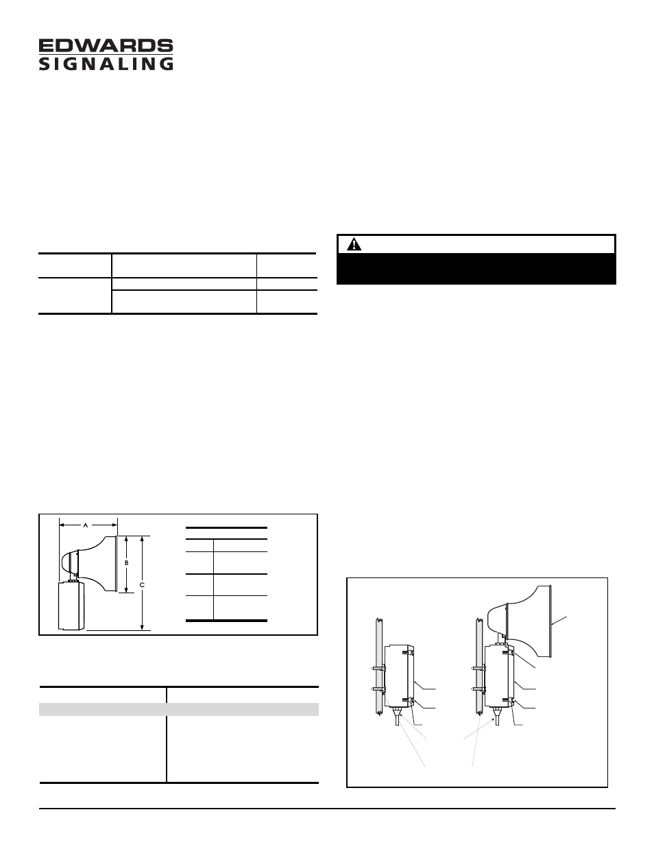
Dimensions
5532M
A
8 7/8"
(225 mm)
B
8 1/4"
(210 mm)
C
13"
(330 mm)
Figure 1. Speaker/Amplifier Dimensions
Installation
The Adaptatone may be mounted to any flat surface or
may be used as a freestanding unit mounted to a rigid
pipe. The Adaptatone must be installed in accordance
with the latest edition of the National Electrical Code or
other regulations applicable to the country and locality
of installation and by a trained and qualified electrician.
NOTE: The increased resistance due to long wire runs
needs to be accounted for in sizing wire.
Consult Applications Engineering for details.
CAUTION
During installation, care must be taken so that components
on the printed circuit board are not damaged.
1.
Mount Adaptatone as shown in Figure 3.
a.
Flat Surface Mounting. Secure unit to
mounting surface using the (4) mounting holes in
the mounting plate on the rear of the box. Use
the #10 x 3" (76 mm) wood screws (furnished loose)
or other hardware (not supplied) suitable for the
mounting surface.
b. Rigid Pipe Mounting. Loosen the (4) cover screws
from the signal box and lift off signal box cover.
NOTE: Cover screws are captive. Do not remove from
cover.
Remove the center knockout in lower wall of box
and mount box to a 1/2" (12.7 mm) conduit pipe
using suitable connector.
2.
Install wires through a knockout hole in the bottom
of the box from a raceway that is, with its connections
to the 1/2" (12.7 mm) conduit knockout hole, approved
for the same degree of protection and enclosure type
needed by the application. Use the provided plastic
tie-wrap, on the barrier to the electronics, to separate
incoming power leads from signal and tone initiating
leads, per NEC (Figure 4).
Figure 3. Adaptatone Mounting
Speaker
Large star nut to
adjust speaker
direction
Signal Box
(4) Cover
screws
Signal Box
(4) Cover
screws
(4) Collar
gaskets
(4) Collar
gaskets
Raceway and connections
(not supplied)
to the 1/2" (12.7 mm)
knockout hole
(4) #10 x 3" (76 mm)
screws or other hardware
suitable for the mounting surface
Voltage
Tone On Current (A)
Speaker/Amplifier - Standard Volume
20V DC
0.63
24V DC
0.74
28V DC
1.0
31V DC
0.85
20V FWR 120 Hz
0.69
24V FWR 120 Hz
0.79