Untitled, Maintenance and test, Warning – Edwards Signaling 5533MD-AW User Manual
Page 2: Detail a, Figure 3. speaker adjustment
2
5.
Secure outlet box cover.
6.
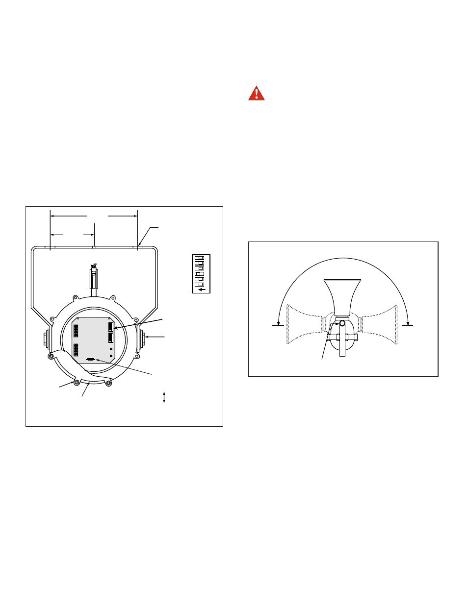
The sound level is factory set to maximum. Adjust volume
level, if desired, by turning potentiometer R72 (Figure 2).
7.
Adjust speaker direction by loosening (2) nuts and pivoting
speaker to desired position (Figure 3). Tighten (2) nuts.
8.
Ensure mating surfaces are clean and undamaged. Secure
housing cover aligning the straight edge of the cover with the
straight edge of the housing. Torque nuts evenly in opposing
pairs to 140 to 150 in-lb. Apply power.
9.
Verify operability.
Maintenance and Test
Figure 2. Adaptatone PC Board and Mounting Holes,
5533M-AQ Model Shown
5"
(127 mm)
2-1/2"
(63 mm)
(3) MOUNTING
HOLES
(2) NUTS,
LOOSEN TO
ADJUST
SPEAKER
DIRECTION
R72, TURN
TO ADJUST
SOUND LEVEL
INCREASE
DECREASE
HOUSING COVER
(8) NUTS
(8) BOLTS
NOTE: FOR CLARITY, ONLY SELECTED COMPONENTS ARE SHOWN.
SPKR (+)
SPKR (-)
6
5
4
3
2
1
ON
6
5
4
3
2
1
ON
6
5
4
3
2
1
ON
DETAIL A
PROGRAMMING
SWITCHES
(SEE DETAIL A)
TB1
TB2
SW2
SW1
Figure 3. Speaker Adjustment
HORN PIVOTS 180°
(2) NUTS, LOOSEN TO ADJUST
SPEAKER DIRECTION
Examine the unit semi-annually for external accumulation of dirt.
Clean if necessary.
The Adaptatone should be tested annually or as required by the
local authority having jurisdiction to ensure continuous service.
WARNING
Do not apply power to the unit until installation is
completed and housing cover and outlet box cover are
secured.