Figure 5. mounting configurations – Edwards Signaling 105DHIST-FJ User Manual
Page 3
P/N 3100394 ISSUE 3
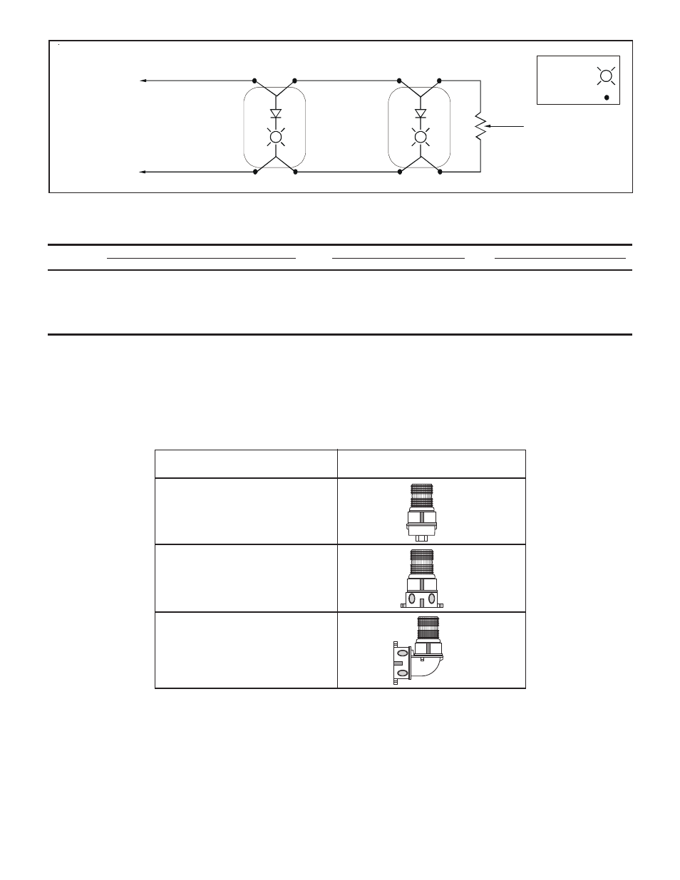
Figure 4. Wiring Diagram for the 105DHIST-FJ Series
NOTE: DC polarity of circuit shown in supervisory state (signal inactive). Circuit polarity to reverse to activate signal.
Electrical supervision requires wire run to be broken at each device.
Device for constant input voltage. Do not connect to “coded” or pulsating voltage.
From Power Source
or
Previous Signaling Device
End-of-Line Resistor,
when required with
supervised system
KEY:
Light symbol -
Wire nut symbol -
(+)
Red
(+)
Red
(+)
Red
(+)
Red
Black
(-)
Black
(-)
Black
(-)
Black
(-)
105DHISTC-FJ
105DHISTC-FJ
(+)
(-)
NOTE: For non-fire alarm stand-alone use tie the two red leads together and tie the two black leads together.
Table 2. 105DHIST-FJ Series Electrical Specifications
Operating Current*
Initial Surge Inrush Current
Repetitive Surge Current
Voltage** RMS Current (A)
Mean Current (A)
Current (A)
Time (mS)
Current (A)
Time (mS)
20V DC
1.08
0.84
2.70
1.10
2.24
450
24V DC
0.95
0.69
2.97
1.13
2.21
400
28V DC
0.85
0.66
3.06
1.24
2.16
381
30V DC
0.83
0.64
3.14
1.27
2.14
360
*Use the operating current to establish the wire gauge and standby power requirements. Consult the control unit manufacturer to
determine surge and peak current effects and maximum number of strobes on the system.
**CAUTION: To prevent damage to the visual signal's internal circuit and to assure its continued proper functioning, DO
NOT operate the unit outside of the Special Application voltage range of 20-30V DC.
105DHIST Series
Mounted on a Cat. No. 105PM Pipe
Mount Attachment
Mounted on a Cat. No. 105BX Outlet
Box Attachment
Mounted on a Cat. No. 105BM
Mounting Bracket with the
Cat. No. 105BX Outlet Box
Attachment
Figure 5. Mounting Configurations