Edwards Signaling 2453BSA User Manual
Page 3
P-047550-1720 ISSUE 3 © 1997
375
373
368
365
360
67
61
60
60
70
125
122
118
115
128
30
90
150
210
270
330
390
20
21
22
23
24
Operating Voltage Full Wave Rectified
Ope
ra
ti
ng Cur
re
nt (mA)
79
70
73
75
78
125
114
115
117
119
50
75
100
125
150
20
21
22
23
24
Operating Voltage DC
O
p
erat
in
g
Cu
rren
t (
m
A)
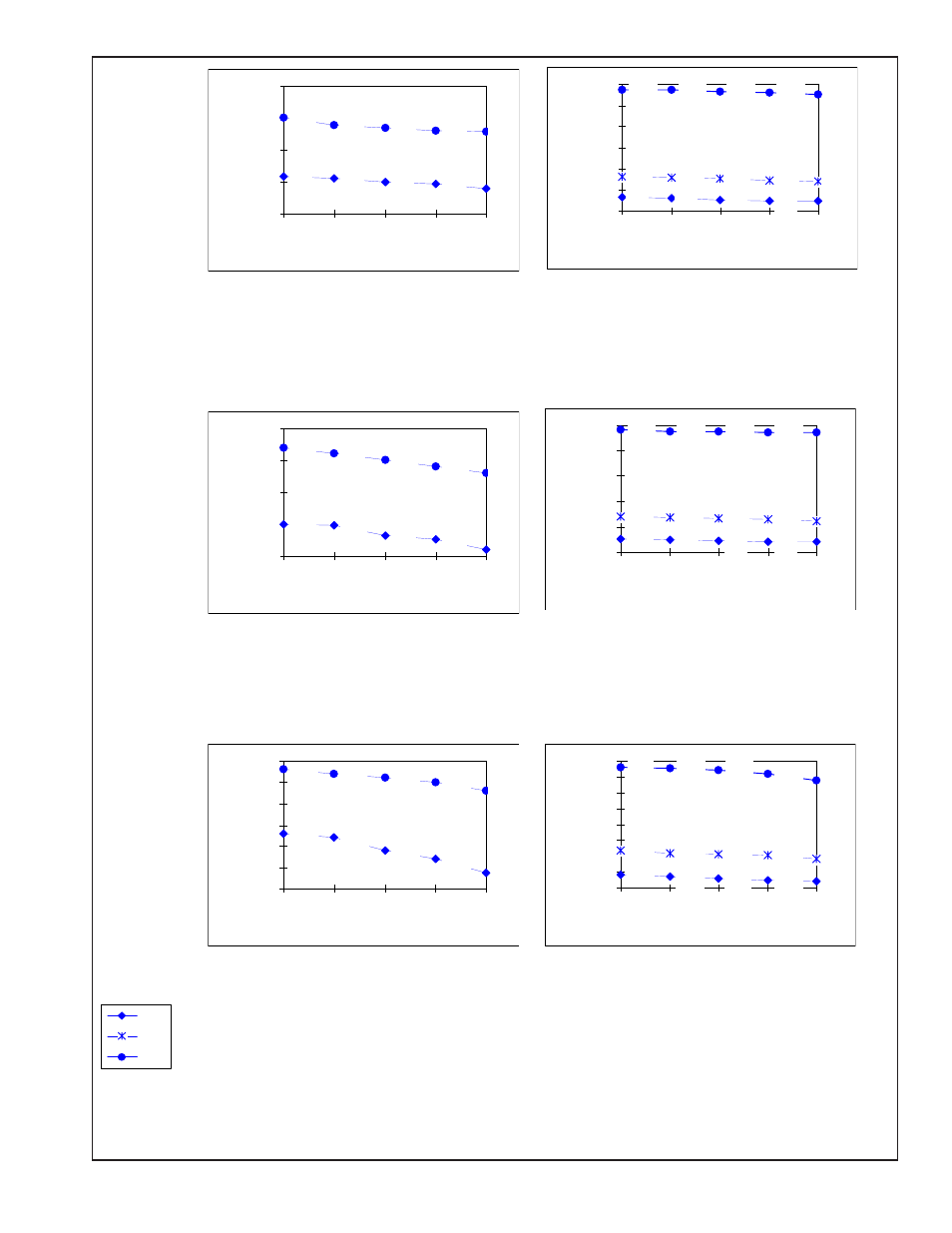
Figure 3. V/I Curves
15 cd Model
Peak Inrush Current @ 24 Vdc = 7.6 A for less
than 50 microseconds.
Peak Inrush Current @ 24 Vdc = 6.6 A for less
than 50 microseconds.
NOTE:
Use the average current rating to establish the maximum number of strobes, wire gauge and standby power requirements. Consult the
manufacturer to determine the peak current effects on the system.
Iavg
Irms
Ipeak
910
900
890
870
828
220
210
200
190
235
370
363
357
330
385
150
250
350
450
550
650
750
850
950
20
21
22
23
24
Operating Voltage Full Wave Rectified
Ope
ra
ti
ng Cur
re
nt (mA)
265
219
235
245
260
340
315
325
330
335
200
225
250
275
300
325
350
20
21
22
23
24
Operating Voltage DC
Ope
ra
ti
ng Cur
re
nt (mA)
Peak Inrush Current @ 24 Vdc = 7.8 A for less
than 50 microseconds.
Peak Inrush Current @ 24 Vdc = 6.8 A for less
than 50 microseconds.
110 cd Model
530
526
524
522
520
98
94
92
90
102
186
181
177
172
190
50
150
250
350
450
550
20
21
22
23
24
Operating Voltage Full Wave Rectified
Ope
ra
ti
ng Cur
re
nt (mA)
125
105
113
116
124
185
165
170
175
180
100
125
150
175
200
20
21
22
23
24
Operating Voltage DC
Ope
ra
ti
ng Cur
re
nt (mA)
30 cd Model and
15/75 cd Model
Peak Inrush Current @ 24 Vdc = 7.6 A for less
than 50 microseconds.
Peak Inrush Current @ 24 Vdc = 6.8 A for less
than 50 microseconds.