Maintenance warning, Warning – Edwards Signaling 103I Series User Manual
Page 2
P/N 3100415 ISSUE 1
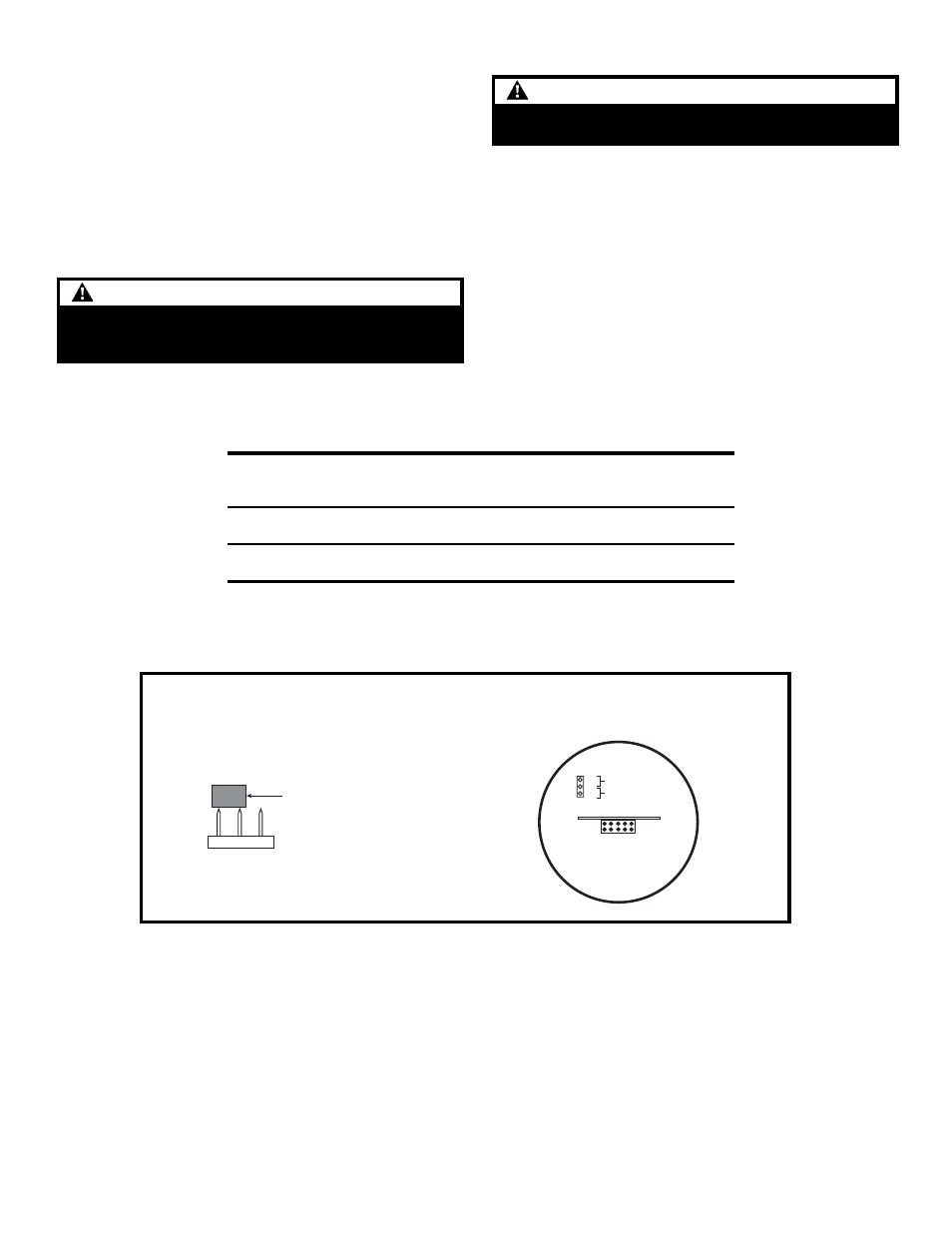
Figure 1. Installing the Jumper
1
2
3
Jumper
(Install on pins 1 and 2
for flashing)
Pin
Location
b.
For DC models: There are four 18" wire leads: black
(common), red (for activation of red LEDs), white with
green stripe or blue (for activation of green or blue LEDs-
-depending on model) and amber (for activation of amber
LEDs).
Using wire nuts, connect black lead to DC common and
connect each of the other three leads to DC hot.
5.
Turn on power and verify that the signal operates properly.
Maintenance
WARNING
To avoid the risk of injury, do not start any maintenance
when unit is energized. Reinstall lens beore energizing
unit.
The module lens exterior surfaces should be periodically cleaned
with a soft clean cloth using water and a mild detergent to main-
tain optimum light visibility. Disconnect power before cleaning.
Lens Replacement
1.
Remove (4) screws securing the lens to the base from bottom
of base and remove lens.
2.
Replace lens on base and secure with (4) screws removed in
step 1.
Steady
Flashing
1
2
3
WARNING
To prevent electrical shock, disconnect power before
removing the lens.
Cleaning
Table 1. PLC Compatibility
Operating
Max. off state
Continuous
Surge
voltage
leakage current
on current
(inrush/duration)
Cat. No.
Volts
mA
mA
A/mSeconds**
103I-RBA-G1
24V DC
5
55
0.070/8
103I-RGA-G1
103I-RBA-N5
120V AC
5
45
0.100/8
103I-RGA-N5
*All AC volts at 60 Hz
** Amps/milliseconds