Edwards Signaling 102 Light Source User Manual
Edwards Signaling Safety
© 2010 UTC Fire & Security. All rights reserved.
1 / 2
P/N 3100701 • REV 3 • ISS 09AUG10
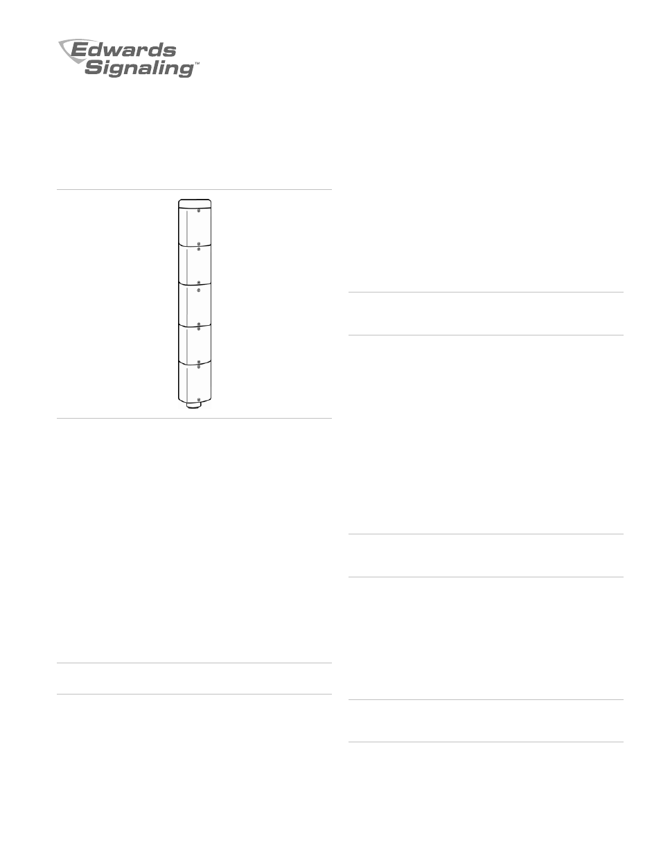
102 Series Triliptical Stackable Beacon Lighting
System Light Sources Installation Sheet
Description / Operation
The Edwards Triliptical Stackable Beacon Lighting System is a
unique audible-visual signaling device that can contain up to 5
light modules and either a single or multiple tone module in a
single "stack."
All components of the Triliptical Stackable Beacon Lighting
System are UL and cUL listed subassemblies. The units,
when assembled, are UL and cUL listed for indoor and outdoor
applications.
The enclosures are NEMA 3R, 4X, and IP65 rated. Each light
source module contains a removable cover to allow for easy
relamping. The light module cover features a molded-in gasket
for dust tight reliability.
Installation
WARNING: To prevent electrical shock, do not connect power
until instructed to do so.
Installation must be in accordance with local codes.
1. Assemble the stackable beacon lighting system (Figure 1).
a. Loosen captive screws and remove cover of affected
lens module.
b. Insert the appropriate light source into board grooves
at bottom of lens ensuring that the four prongs on the
PC board are aligned with the plug located in the back
of the lens assembly.
NOTE: When using LED light sources, ensure that the color
of the LED light source and the color of the lens assembly
match.
WARNING: To prevent leakage, ensure the magnifier ring on
the lens cover and the magnifier ring on the lens module are
aligned (Figure 1).
c.
Place the lens module cover on the front of the lens
module and secure using two captive screws.
d. Repeat steps a through c for any remaining modules
(up to 5).
e. Once the last module has been assembled, place the
cap on top and secure the cap with the captive screw.
2. Apply power to the unit and verify proper operation.
NOTE: For further installation details, see the instructions
supplied with the lens modules, P/N 3100700, or the
instructions supplied with the base, P/N 3100669.
Maintenance
WARNING: To prevent electrical shock, disconnect power to
all modules. Wait 5 minutes for stored energy in strobe
modules to dissipate before working on unit.
Light Source Replacement
1. Loosen captive screws and remove cover of affected lens
module.
2. Remove the light source assembly from the lens module.
3. Install new light source assembly ensuring that the four
prongs on the PC board are aligned with the plug located
in the back of the lens module.
WARNING: To prevent leakage, ensure the magnifier ring on
the lens cover and the magnifier ring on the lens module are
aligned (Figure 1).
4. Replace lens cover and secure using two captive screws.