Wiring diagram for category 4, Ce compliance information, General specifications – Edwards Signaling 383-BT User Manual
Page 3
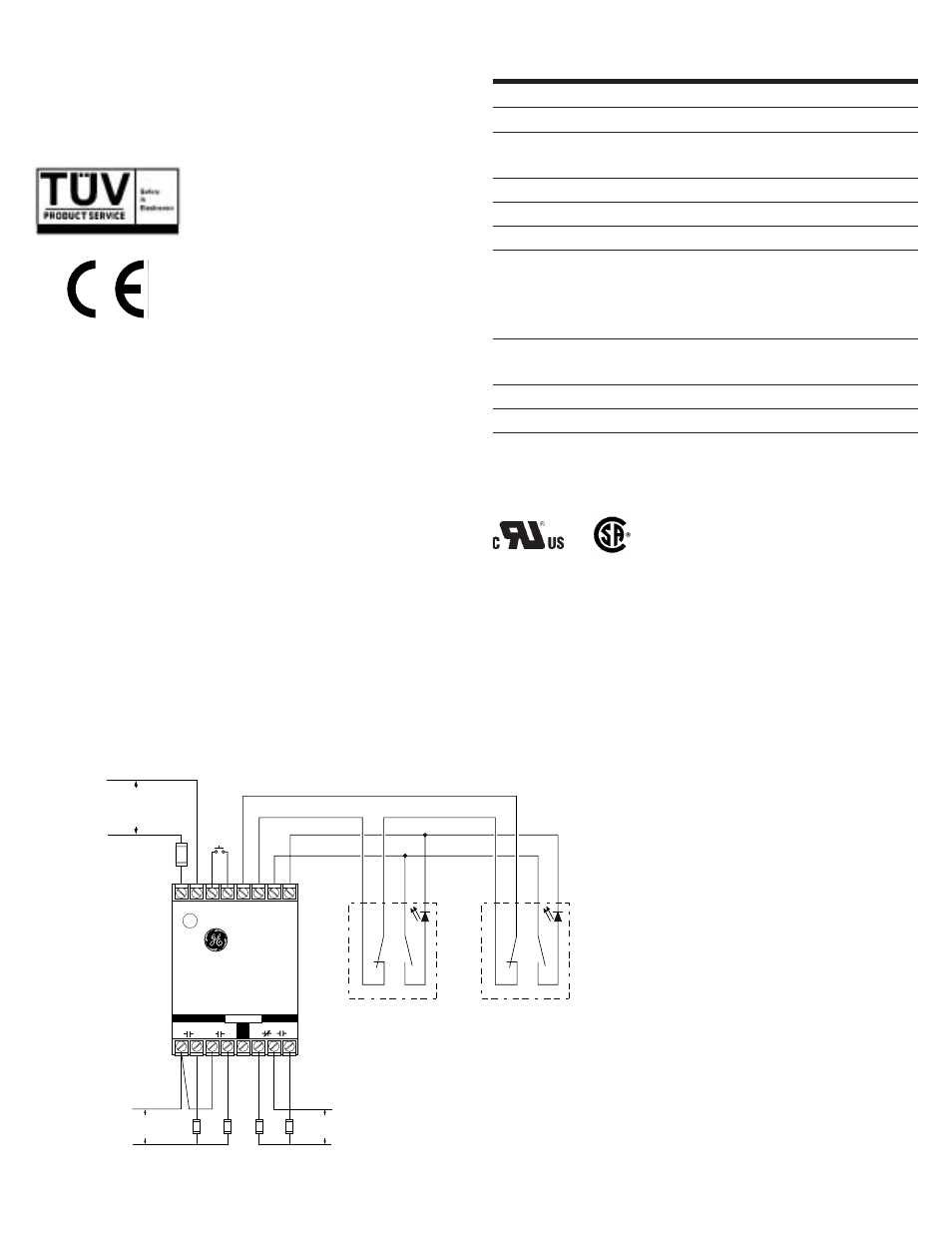
Wiring Diagram for Category 4
Inputs shown with safety gate/guard in closed position. Two Series 300-B GuardSwitches™ with one INT relay are required for each safety gate.
When first applying the INT Safety Monitor Relay, the inputs must be cycled to check for proper operation before the output contacts close. To cycle the inputs, the guard must be
opened and then closed. This start-up test is sufficient; however, we recommend that the proper operation of the switches and relay be checked at least every 24 hours.
These switches are TUV certified for CE applications only when used with the INT
Safety Monitor Relays. See Risk Category 3 and Category 4 wiring diagrams above.
CE Compliance Information
*300-BLT-
*Or other DPST GuardSwitch
(See the 300-BT Series
installation instructions)
( – )
( + )
INT-03-230: 230V AC
INT-03-120: 120V AC
INT-03-024: 24V DC
R e q u i r e d F a s t o r
S l o w - A c t i n g F u s e :
( 2 5 0 V , 5 x 2 0 m m F )
I N T - 0 3 - 2 3 0 : 4 0 m A
I N T - 0 3 - 1 2 0 : 8 0 m A
I N T - 0 3 - 0 2 4 : 1 / 4 A
Required Fast or
Slow-Acting
Fuses: 4A (250V,
5x20 mm F
W
H
T
B
L
K
R
E
D
B
L
U
*300-BLT-
W
H
T
B
L
K
R
E
D
B
L
U
Note – The LED on the BLT model
will be ON when the guard is open
Fuses: 1A (250V)
RESET
A
SAFE
AUX.
B
C
D
E
F
G
OUTPUTS
230 VAC
60 VDC
120 VAC
30 VDC
LOADS
–
+
L1
L2
1
2
X1 X2
Y1
Y2
N.O.
N.C.
Safety Monitor Relay
INT-03
General Specifications
Enclosure
Coated Aluminum
Temperature Range
-40
°
F to 180
°
F (-40
°
C to 80
°
C)
Environmental
Hermetically Sealed Contact Switch
Encapsulated in Polyurethane
NEMA Rating
1, 2, 5
Protection Class
IP 64
Response Time
1 msec
Individual circuits
The two circuits do not switch simultaneously, and depend
on the speed of the guard closure. Based on closure speed
of 1' per second and a gap of 1/8", a delay less than
50 msec is typical.
Life Cycles
100,000 Under Full Load;
Up to 200,000,000 Under Dry Circuit
Conduit Connection
1/2" Threaded NPT
UL/CSA/TUV
All Models
File E 122942
LR89176
Declaration of Conformity
available upon request.
GE Security Industrial
GuardSwitch
TM
Series 300
www.ge-security.com/industrial