Edwards Signaling Genesis Low Frequency 520 Hz Horn User Manual
Description, Installation
© 2014 UTC Fire & Security Americas Corporation, Inc.
1 / 4
P/N 3102148-EN • REV 02 • ISS 25MAR14
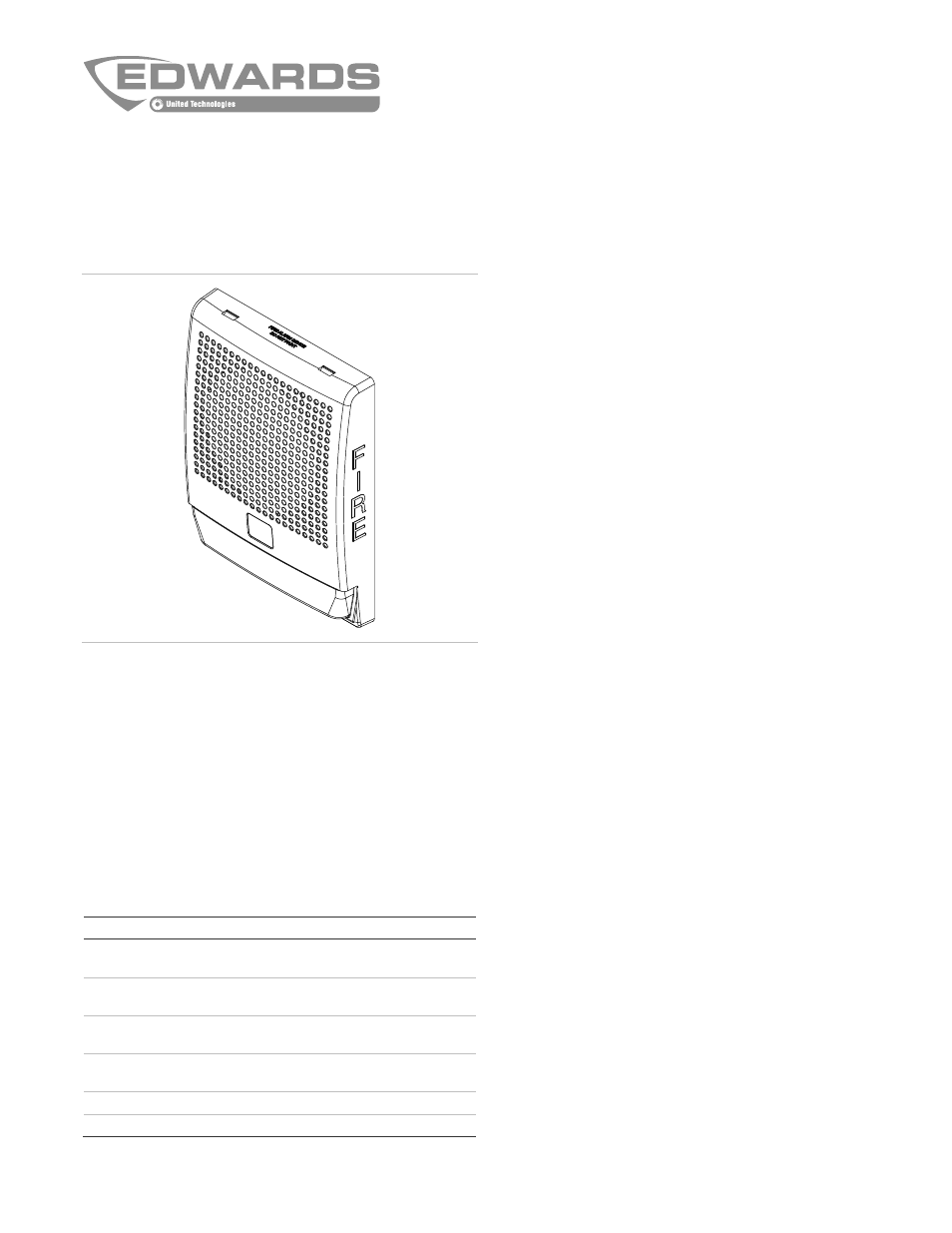
Genesis Low Frequency (520 Hz) Horn
Installation Sheet
Description
The Genesis Low Frequency (520 Hz) horn can be used for
applications where a low frequency alarm notification appliance
is required. The device is designed for indoor use only and can
be mounted on the wall or ceiling. See Table 1 for a list of
model numbers.
The horn includes field-configurable jumper options for
selecting:
•
Temporal or steady horn output
•
High dB or low dB output
Table 1: Models
Description
Number
Low frequency (520 Hz) horn, white housing,
no FIRE marking
G4LFWN-H
Low frequency (520 Hz) horn, white housing,
with FIRE marking
G4LFWF-H
Low frequency (520 Hz) horn, red housing, no
FIRE marking
G4LFRN-H
Low frequency (520 Hz) horn, red housing,
with FIRE marking
G4LFRF-H
Surface mount box, white housing
G4B
Surface mount box, red housing
G4RB
Installation
Install and wire this device in accordance with applicable
national and local codes, ordinances, and regulations.
Note:
Electrical supervision requires that you break the wire
run at each terminal. Do not loop wires around the terminals.
To install the horn:
1. Remove the cover by using a screwdriver to depress and
slightly twist both tabs on top of the unit.
2. Set the horn signal and sound output level to desired
settings. See Figure 1.
To change the horn output level from high dB to low dB,
cut jumper JP3.
To change the horn signal from temporal to steady, cut
jumper JP2.
3. Mount the horn as follows.
Note:
Route the signal circuit field wiring through the
cutout in the center of the horn.
Flush mount:
Mount the horn and flush mount spacer
onto a compatible electrical box (Figure 2), making sure
not to overtighten the mounting screws. See
“Specifications” for compatible electrical boxes.
Surface mount:
Mount the G4B or G4RB surface mount
box on the wall or ceiling (Figure 3), and then secure the
appliance to the box using the screws provided with the
box.
4. Connect the signal circuit field wiring to the horn terminals
(Figure 4). Observe polarity for the unit to function
properly.
5. Replace the cover by aligning it at the bottom, and then
snapping it in at the top (Figure 2 and Figure 3).
6. Test the unit for proper operation.