Required for each safety gate, Series circuit parallel circuit, Figure 1 – Edwards Signaling 343-BT User Manual
Page 2
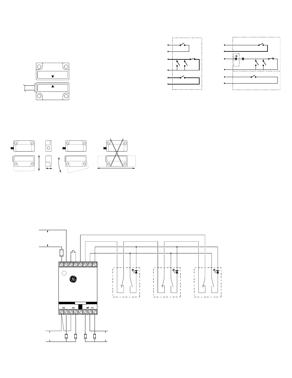
Perpendicular
Actuation
Door
Actuation
Parallel Actuation
Best
Best
Not Recommended
Pivot Actuation
Good
The parallel actuation can result in on/off/on signal if the actuator passes by the
switch rather than coming to rest in proximity to it. This is NOT a recommended
configuration for safety interlock applications.
Figure 2
Mounting Configurations
Wiring Diagram for Category 3
Inputs shown with safety gates/guards in closed position. One Series 300-BT GuardSwitch
™
required for each safety gate.
*300-BLT-
*Or other DPST GuardSwitch
(See the 300-BT Series installation instructions)
( – )
( + )
INT-03-230: 230V AC
INT-03-120: 120V AC
INT-03-024: 24V DC
R e q u i r e d F a s t o r
S l o w - A c t i n g F u s e :
( 2 5 0 V , 5 x 2 0 m m F )
I N T - 0 3 - 2 3 0 : 4 0 m A
I N T - 0 3 - 1 2 0 : 8 0 m A
I N T - 0 3 - 0 2 4 : 1 / 4 A
Required Fast or Slow-
Acting Fuses: 4A (250V,
5x20 mm F
W
H
T
B
L
K
R
E
D
B
L
U
*300-BLT-
W
H
T
B
L
K
R
E
D
B
L
U
Note – The LED on the BLT model will be ON when the guard is open
Fuses: 1 A (250 v)
Multiple DPST GuardSwitches – Shown with actuators in position, all guards closed.
The L.E.D of the BLT model will be on when the guard is open. If multiple guards
are open, L.E.D will be dimmer. The maximum number of GuardSwitches that can
be used is 50, although troubleshooting and line resistance must be considered.
(Do not exceed 30 Ohms of combined contact and line resistance. Each GuardSwitch
will have less than 0.5 Ohms of resistance.)
RESET
A
SAFE
AUX.
B
C
D
Safety Monitor Relay
INT-03
E
F
G
OUTPUTS
230 VAC
60 VDC
120 VAC
30 VDC
LOADS
*300-BLT-
W
H
T
B
L
K
R
E
D
B
L
U
Series Circuit
Parallel Circuit
–
+
L1
L2
1
2
X1 X2
Y1
Y2
N.O.
N.C.
A resistor can be added in series to limit the inrush current (at least 48 Ohms for
24V applications). The resistor can be added in series just before the load. The
voltage drop and the power rating of the resistor must be considered. Voltage
drop = I•R; Watts = I
2
R (I = maximum continuous current of the load).
6. When mounting the switch on an ungrounded machine, ground the switch housing
by connecting your ground lead to one of the switch mounting screws.
S1
BLK
WHT
BLUE
RED
BRN
ORG
S2
S3
S4
CIR. 2
CIR. 1
S5
CIR.3
*Circuits shown with magnet actuator away from switch.
S1, S5
Normally open reed switch, closed when actuator is within 0.38"
S2, S3
Normally open reed switches, will close if misaligned or tampered with
a standard magnet
S4
Biased closed reed switch, open when actuator is between 0.12" and 0.38"
S5
Normally open reed switch, closed when actuator is within 0.38".
N.O. circuit: Black and white wires.
N.C. biased tamper circuit: Red and blue wires.
N.O. monitor circuit: Orange and brown wires.
Circuits
without LED
Circuits
with optional LED
S1
BLK
WHT
BLUE
RED
D1
D2
S2
S3
S4
CIR. 2
CIR. 1
S5
ORG
BRN
CIR. 3
Optional LED
sensing face
sensing face
Figure 1
GE Security Industrial
GuardSwitch
TM
Series 300
www.ge-security.com/industrial